5 Common Mistakes to Avoid in MCAD mechanical Engineering Drawings
- Posted On:
- September 17, 2024
- Category:
- Mcad
Mechanical Engineering Drawings
Before the digital era, detailed scaled drawings were meticulously created on paper using pencils and drafting tools. The process was time-consuming and fraught with human error, as any modification required laboriously redrawing the entire blueprint.
The introduction of Computer-Aided Design (CAD) software marked a significant turning point in 1980s.
CAD systems enabled engineers to create precise digital drawings, leveraging features such as layering and automated dimensioning. This transition significantly enhanced the accuracy and efficiency of the design process, reducing manual errors and saving time.
The 1990s saw the rise of 3D CAD systems, allowing engineers to create three-dimensional models of components and assemblies. This provided a more intuitive and realistic view of the design.
Modern CAD systems introduced parametric design, where changes to one part of the model automatically update related components.
This made managing complex assemblies more manageable.
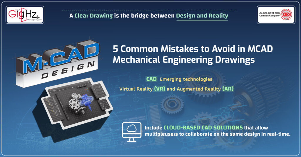
Recent advancements include cloud-based CAD solutions that allow multiple users to collaborate on the same design in real-time.
Modern CAD tools provide high-quality rendering and visualization features, allowing designers to create photorealistic images and animations of their models. This aids in better presentations and decision-making.
Emerging technologies like virtual reality (VR) and augmented reality (AR) are being used to interact with 3D models in immersive environments, enhancing design review and validation processes.
Furthermore, CAD systems now integrate seamlessly with manufacturing processes through Computer-Aided Manufacturing (CAM) and additive manufacturing (3D printing). This streamlines the transition from design to production.
The concept of digital twins involves creating a virtual replica of physical assets to monitor and optimize performance throughout their lifecycle.
From manual blueprints to sophisticated 3D modeling and cloud-based collaboration, these developments have significantly enhanced the efficiency, accuracy, and functionality of engineering drawings.
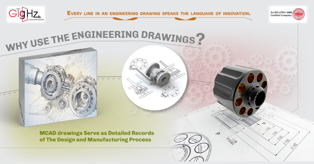
Why use the Engineering Drawings?
MCAD engineering drawings provide detailed and accurate specifications of mechanical components. Without these precise drawings, the risk of design errors increases, which can lead to incorrect dimensions and fit issues.
By providing exact specifications and instructions, MCAD engineering drawings streamline the manufacturing process.
MCAD drawings serve as detailed records of the design and manufacturing process. They document every aspect of the design, including changes and material specifications. This documentation is crucial for future maintenance, repairs, and upgrades. Without it, tracking design history and making informed modifications would be difficult.
Quality control teams compare finished parts against these drawings to ensure they meet the design standards. Without these drawings, maintaining quality would be more challenging, increasing the likelihood of defective parts reaching the final product.
5 Common Mistakes to Avoid in MCAD mechanical Engineering Drawings
Engineering drawings are crucial in the automotive industry, where precision and reliability are paramount. They ensure that components like battery brackets are manufactured to exact specifications, fitting perfectly within the vehicle’s chassis and performing reliably under various conditions.
Let’s consider designing an automotive component, such as a bracket used to secure a battery pack in an electric vehicle.
This component needs to meet precise specifications to ensure safety and performance.
1. Inaccurate Dimensions

Dimensioning is crucial in the manufacturing process.
Suppose the design drawing for the battery bracket specifies that it should fit into a designated slot within the vehicle’s chassis. If the dimensions are inaccurate, the bracket might not fit correctly, causing issues during assembly.
How to avoid?
For instance,
Specifying a hole diameter as 10.123456 mm instead of 10 mm.
Use practical precision. Specify dimensions like 10 mm instead of overly precise figures. CAD systems and machining tools are optimized for standard precision, and excessive detail can lead to confusion and unnecessary complexity.
Double-check all measurements and use precise dimensioning standards. Always ensure that dimensions are clearly marked and referenced from the correct datum points. Implementing rigorous checking procedures and peer reviews can also help catch these errors early.
1. Excessive Fillet Radius
Fillets are design features that must be either included or excluded entirely during the design phase, with no middle ground. This often leads to significant design errors, particularly in CNC machining and prototype injection molding. Unlike 3D printing, which does not require fillets due to its additive process, traditional manufacturing methods rely on them.
Fillets are used for stress relief, enhancing aesthetics, and adding strength to parts. However, applying an incorrect fillet radius can negate these benefits.
How to avoid?
Fillets should be applied only in the following situations:
- Internal edges where vertical walls meet at an angle less than 180 degrees.
- Internal edges between angled or organic surfaces with an angle of less than 180 degrees.
3. Lack of Tolerances
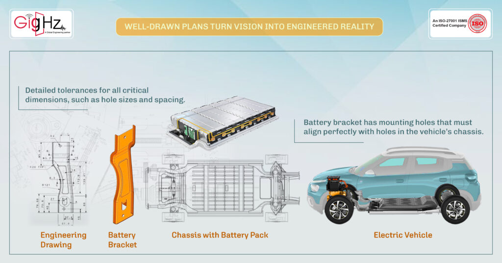
The battery bracket has mounting holes that must align perfectly with holes in the vehicle’s chassis. Without specifying tolerances, there could be misalignment issues during assembly. For instance, if the holes are meant to be 8 mm in diameter but are not specified with tolerances, they might end up being too tight or too loose, affecting the bracket’s fit and function.
How to avoid?
Include detailed tolerances for all critical dimensions, such as hole sizes and spacing. Use appropriate tolerance standards to ensure the holes are within acceptable limits for assembly.
1. Inconsistent Layer Usage
During the design of the battery bracket, if different layers are used inconsistently (e.g., mixing hidden lines with section views on the same layer), it could lead to confusion about which features are visible and which are not. This can result in manufacturing errors or misinterpretation of the design.
How to avoid?
Establish and adhere to a consistent layer naming convention. Ensure that hidden lines, section views, and other design elements are clearly separated into their designated layers.
2. Missing Annotations and Labels
If the design drawing of the battery bracket does not include labels for material specifications or assembly instructions, the manufacturer might use the wrong materials or fail to follow critical assembly steps.
For example, if the bracket is supposed to be made from high-strength aluminum but this is not indicated on the drawing, the manufacturer might use a less suitable material.
How to avoid?
- Comprehensive Annotation Standards: Use ISO 7200 for drawing and design documentation to include essential annotations such as material specifications, heat treatment requirements, and assembly instructions.
- Integrate Bill of Materials (BOM): Embed a detailed BOM within the drawing to specify materials, part numbers, and any special instructions. Tools like SOLIDWORKS and Autodesk Inventor offer integrated BOM features.
- Employ CAD Tools for Automatic Annotations: Use MCAD tools to automate the addition of standard annotations and labels based on the component specifications. For example, Solid Edge’s Drafting tools can automatically generate annotations.
Final Thoughts
Avoiding common errors in MCAD mechanical engineering drawings is key to achieving accurate and effective designs.
By focusing on detail precision, dimensional accuracy, timely revisions, clear communication, and adherence to standards, you can prevent costly mistakes and enhance your project outcomes.
Attention to these aspects ensures smoother processes and successful results in your engineering projects.
Need tailored solutions? Discover how our services can meet your needs today! https://gighz.net/services/
Design Beyond Boundaries—Get in Touch for Top-Tier MCAD Solutions! https://calendly.com/gighz/30min
Table of Contents
Latest Post
Get Customized Engineering CAD Design Service

Book a Free Consultation Call
Partner with Gighz and bring your most innovative design concepts to life. Our engineering cad services accelerate development so you can focus on your big vision.