Mechanical Engineering Drawing
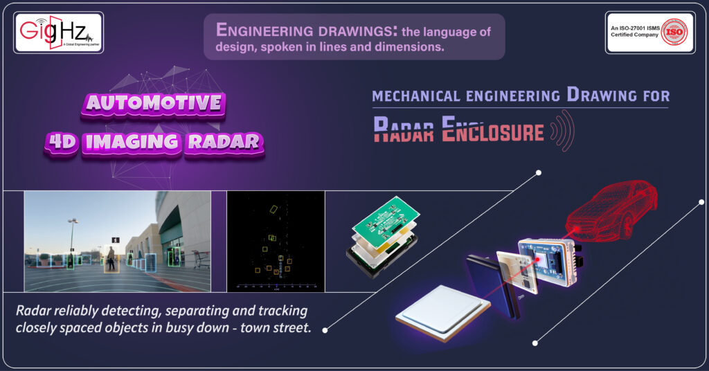
Imagine the Radar Enclosure in your car’s ADAS system as a superhero cape for the radar – it shields the vital components from the elements, like raindrops, pesky dust, and even wild temperature swings.
This protective layer ensures that the radar functions at its best, staying robust and reliable over time.
Now, why is this so awesome?
With the Radar Enclosure guarding the radar gear, the system becomes a precision instrument, spotting objects with accuracy and clarity.
It’s like having a watchful eye on the road, alert to every movement and obstacle, making your driving experience not just safer but smarter too.
So, next time you drive, remember that hidden within your car’s ADAS setup is this quiet champion – the Radar Enclosure, silently ensuring that your radar system performs at its peak, keeping you safe and sound on the road.
How cool is that?
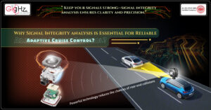
Now, let’s talk about the cool stuff – the Automotive 4D Imaging Radar.
This radar system is like having eyes all around your vehicle, using four dimensions (that’s 3D space plus time) to give you a real-time view of what’s happening on the road.
It’s the secret sauce behind features like adaptive cruise control, dodging accidents, and even paving the way for cars that can drive themselves by keeping an eagle eye on what’s going on around them.
Let’s showcase our journey of creating the mechanical engineering drawing for the ADAS Radar enclosure that we developed,
Basics Components of an Engineering Drawing
Basics for Engineering Drawing involves generating ideas and concepts for creating technical drawings that accurately represent the design and function of a machine or component.
This process often includes exploring different types of views such as isometric, orthogonal, and top views to show the shape and dimensions of the object.
Orthographic projection is commonly used to represent the object’s physical boundaries and design intent. Furthermore, section views may be used to showcase internal features and part numbers. The use of dimensioning and tolerances ensures that the manufacturing drawings meet the requirements of an engineering part.
CAD software plays a significant role in creating accurate drawings with extension lines, arrowheads, and title blocks that provide information about the drawing.
When brainstorming for engineering drawing, it is essential to consider the different types of lines that are used to represent various features such as hidden lines and dimension lines.
Multiview drawings may be used to show the object from different angles, including the front view and top view. The cutting plane technique can be applied to create section views that reveal the internal components of the machine.
Moreover, drawings often include a scale to ensure that the dimensions accurately represent the size of the object.
Drawing standards dictate the format and layout of the drawing, including the placement of the title block and the drawing number for identification purposes.
Challenges we Faced
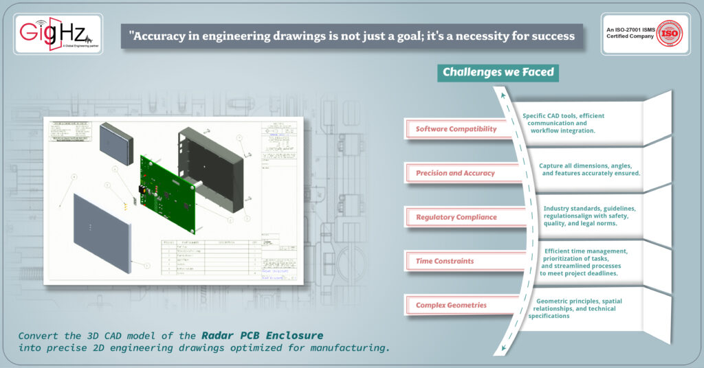
The client has given us the responsibility of transforming their Radar PCB Enclosure (3D CAD model) into accurate 2D engineering drawings tailored for manufacturing purposes.
The challenges we faced are,
Software Compatibility:
Involves effectively navigating and harmonizing multiple versions of CAD software to facilitate seamless collaboration among team members working on the project. By ensuring that everyone can work cohesively regardless of the specific CAD tools they use, this aspect fosters efficient communication and workflow integration within the project.
Precision and Accuracy:
Focuses on the critical task of translating detailed 3D models into precise and faithful 2D representations. This process demands meticulous attention to detail to capture all dimensions, angles, and features accurately, ensuring that the resulting engineering drawings are a true reflection of the original design intent and are ready for manufacturing without any discrepancies.
Regulatory Compliance:
Encompasses the essential aspect of adhering to established industry standards, guidelines, and regulations during the creation of engineering drawings. By following these compliance requirements meticulously, the drawings produced align with safety, quality, and legal norms, thus guaranteeing that the final product meets all necessary certifications and approvals.
Time Constraints:
Represents the challenge of producing high-quality engineering drawings within a restricted timeframe. This factor necessitates efficient time management, prioritization of tasks, and streamlined processes to meet project deadlines without compromising on the accuracy and completeness of the drawings, ensuring timely delivery and project success.
Complex Geometries:
Involves the intricate task of clearly and succinctly dimensioning complex assemblies and components within the engineering drawings. This demands a deep understanding of geometric principles, spatial relationships, and technical specifications to accurately represent the intricacies of the design in a comprehensible manner, enabling effective communication and manufacturing of the final product.
Balanced mechanical engineering Drawing for Radar Enclosure
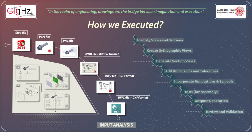
Input Analysis
Upon analyzing the inputs provided by the client, it is evident that they have shared 3D models encompassing both individual enclosure parts and the assembly. The breakdown includes an Enclosure Assembly file (A1) along with specific parts such as the Top Casing (P1), Bottom Casing (P2), Switch (P3), Switch Holder (P4), and Light Pipe (P5).
In terms of requirements, the client has outlined the desired formats for the drawing files and outputs to align with their needs.
Specifically, for the Part 3D Model, the client expects the following deliverables: a Part file in sldprt format, a STEP file in STEP AP214 format, drawings in DXF and PDF formats, a Drawing File in slddrw format, and a PNG file showcasing the 3D model.
This comprehensive analysis sets the stage for meeting the client’s expectations and ensuring that the resulting engineering drawings are crafted precisely as per their specifications and preferences.
Work Outline
Identify Views and Sections:
We kick off by identifying the crucial views and sections needed to accurately portray the 3D models in our 2D drawings.
This helps us ensure that every angle, detail, and aspect is captured for a comprehensive representation.
Create Orthographic Views:
We then dive into creating precise orthographic views, laying down a clear and structured depiction of the parts and assembly. These views form the foundation for further detailing and annotation, guiding our design process.
Generate Section Views:
Delving deeper, we generate section views to explore the internal structures of the components, offering an intricate look into the assembly’s composition and design intricacies hidden from external views.
Add Dimensions and Tolerances:
Our next step involves adding accurate dimensions and tolerances to the drawings, guaranteeing manufacturing precision and alignment. By detailing measurements and specifications, we provide a roadmap for seamless production.
Incorporate Annotations & Symbols:
We enrich the drawings by incorporating annotations and symbols that offer additional context and information. These elements clarify specific details, materials, or processes, enhancing the overall comprehension of the engineering specifications.
BOM (for Assembly):
We meticulously prepare a comprehensive Bill of Materials (BOM) for the assembly, listing out all the necessary components, parts, and quantities essential for the fabrication process. This detailed inventory streamlines the sourcing and assembly procedures.
Review and Validation:
Prior to finalization, we conduct a rigorous review and validation process to ensure that our engineering drawings adhere to the client’s requirements and industry standards. This meticulous step guarantees the quality and accuracy of our work.
Outputs Generation:
Finally, we consolidate all the refined drawings, annotations, and specifications to generate the conclusive outputs. This phase sees us compiling detailed views, sections, and dimensions into polished engineering drawings ready for client evaluation and subsequent manufacturing stages.
Review and Validation
During the review stages, the following points are thoroughly examined, and their accuracy and compliance are verified:
- Dimensional Accuracy ensure that the sufficient dimensions for manufacturing
- Critical dimension mentioning
- Duplicate dimension removing Clarity of Views Annotation and Labeling Tolerances and Fits Bill of Materials (BOM) Accuracy Consistency Across Drawings
- Client Specifications
- Quality of Graphics
All the files were meticulously reviewed, and the outputs were generated in their respective required formats.
Why we Do?
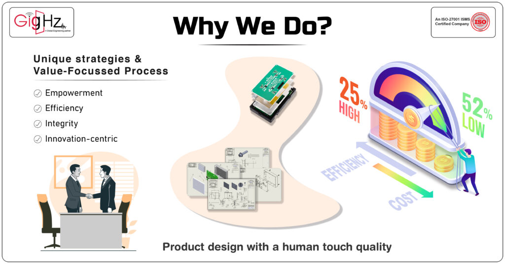
We challenge our MCAD capabilities with emerging Automotive technologies to keep your time and cost in control, thereby transforming product design with human touch quality.
Despite the challenges in technology, we stand out from the competition due to our innovative methods and value-driven process.
This approach enables us to achieve a significant cost reduction of 52% while simultaneously increasing operational efficiency by 25%.
Our Memorable Achievement: Engineering as a Service (EaaS)
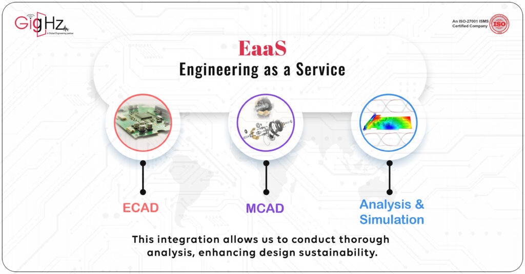
Absolutely! With the increasing prevalence of intricate engineering challenges, our Engineering as a Service (EaaS) offering is undeniably enhancing its impact.
We are harnessing the collective capabilities of ECAD, MCAD, and Analysis & Simulation, positioning us as frontrunners in the industry.
What’s especially thrilling is our provision of an all-encompassing solution that spans the entirety of the engineering workflow.
It’s truly invigorating!
Conclusion
The assembly drawing for the radar enclosure provides a comprehensive view of the design, incorporating both the isometric and side views of the enclosure. The isometric drawing, also known as a three-dimensional mechanical drawing, helps to convey the design concept in a realistic and easy-to-understand manner.
In addition, engineering drawings use parallel lines and numerical callouts to indicate specific measurements and components of the design. The inclusion of an auxiliary view, such as an a-a side view, further aids in understanding the spatial relationships between the various parts of the enclosure.
These technical drawings play a crucial role in manufacturing as they help machinists and engineers understand the shape, dimensions, and materials required to manufacture the product accurately.
Furthermore, the use of computer-aided design tools allows for precise scaling of the drawing and can also be used to generate machine instructions for computer numerical control (CNC) machines.
Discover What We Do Best. Check Out Our Service Offerings! https://gighz.net/services/
Balanced mechanical engineering Drawing for Radar Enclosure
Our Notable Upgrade: Engineering as a Service(EaaS)
Book a Free Consultation Call
Partner with Gighz and bring your most innovative design concepts to life. Our engineering cad services accelerate development so you can focus on your big vision.
Related Blogs