Amazing Ideas and Tips for designing the PCB Enclosure Design
- Posted On:
- July 17, 2024
- Category:
- Mcad

PCB Enclosure Design Tips
Hey there!
Consider the impact on our bodies if we were without skin—it would undoubtedly have significant effects.
Similarly, when designing electronic enclosures for PCBs, the enclosure plays a crucial role akin to skin, influencing the functionality and overall well-being of the electronics housed within.
In the realm of electronics projects, where intricate wiring and numerous components are common, the presence of enclosures is paramount.
These enclosures serve the dual purpose of organization and safety, signifying a deliberate design approach to the product’s usage and handling.
This leads to a fundamental question:
What is the process for creating the appropriate enclosure for the project?
Amazing Ideas and Tips for designing the PCB Enclosure Design
All you require to commence designing the ideal enclosure is encompassed in the following tips,
Make a list of requirements
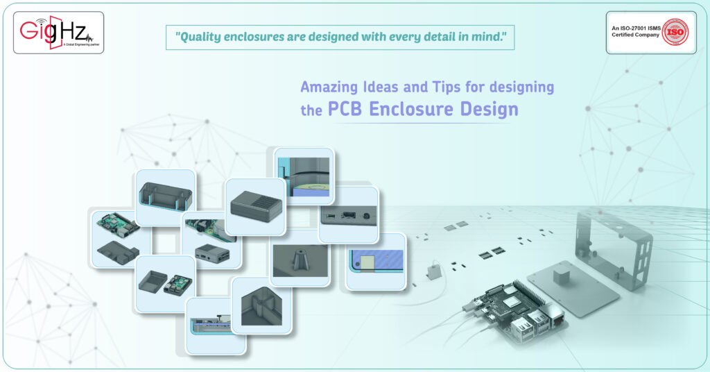
Initially, ask yourself what parts will go inside the casing, what they will do, and how they will interact with the environment. For instance, if your project has a LED light, you might need to include a hole unless the casing is see-through. If you have a list of materials (like a BOM), use it to ensure you have space for all the components.
These answers will give you a list of needs, keeping it short gives you more flexibility for trying out different ideas. You can add more requirements after testing your initial designs.
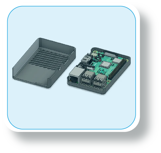
It’s best to design the components before creating the casing. If you’re using common parts like a Raspberry Pi or Arduino, look up their sizes online or find 3D models to help you position them perfectly in the casing.
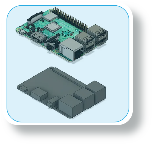
Shell thickness
The first step in designing the enclosure is to decide on the thickness of the outer shell. By this stage, you should have a plan for how you’ll make the enclosure.
The way you manufacture the enclosure affects how you design it. For injection molding, it’s best to have a consistent shell thickness so the plastic flows smoothly.
If you’re using FDM 3D printing, which stands for Fused Deposition Modelling, you need a shell thickness of at least 0.8mm or twice the size of the printing nozzle diameter.
Holding components in place
The first step in designing the enclosure is to decide on the thickness of the outer shell. By this stage, you should have a plan for how you’ll make the enclosure.
The way you manufacture the enclosure affects how you design it. For injection molding, it’s best to have a consistent shell thickness so the plastic flows smoothly.
If you’re using FDM 3D printing, which stands for Fused Deposition Modelling, you need a shell thickness of at least 0.8mm or twice the size of the printing nozzle diameter.
Holding components in place
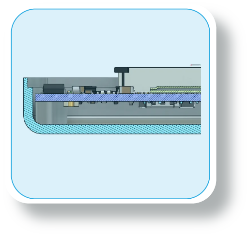
Now is the time to determine how the components will fit inside the enclosure. Prioritize functionality and ease of access over looks.
This step is crucial, especially for fragile or electronic parts. Use support ribs to secure delicate items like printed circuit boards (PCBs) in place. If you’re creating your own PCB, remember to include mounting holes for added safety. For devices with electrical components, consider the placement of wires and connection points when installing the board in the enclosure.
Ensure all cables are neatly arranged inside the enclosure. Think about incorporating strain relief features where cables may be moved or bent. Check that all connection ports are easily reachable. Add adequate supports to safeguard cables and connectors as needed.
Component accessibility
Table of Contents
Latest Post
Get Customized Engineering CAD Design Service

A crucial aspect to decide is how you will reach the components.
Who will need to access them and how quickly and easily should they do so?
The simplest option is to seal the enclosure shut, but this makes the components inaccessible. However, you might need to reach these parts later, like for changing a battery. Two
convenient solutions are using sliding panels or screws.
They are easy to include and can be combined. Other options include snap closures and traditional hinges, but they require careful attention as they are more sensitive to exact measurements. Living hinges also have limitations on the materials they can be used with, as frequent use may cause them to break.
Fillet corners and edges
Likewise, designs that ease cable tension can lower the strain on cables, while fillets decrease stress on the corners and edges of your enclosure. Including fillets on all edges, even with a small radius (0.1mm), helps maintain a uniform shell thickness without extra material.
It’s also vital to think about manufacturing needs. Rounded corners can enhance the quality of 3D prints, and sharp edges should be steered clear of in injection molding designs. Apart from reducing stress points, fillets boost ergonomics and enhance the appearance of the enclosure.
Increase rigidity with ribs and gussets
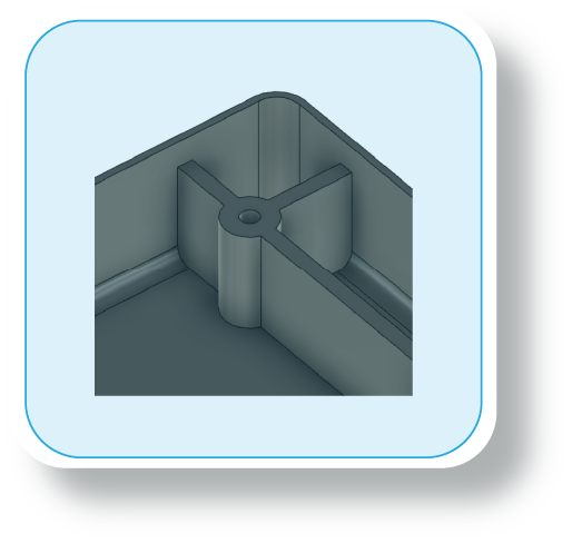
Once support ribs are in place to secure the components, the next step is to reinforce the enclosure. Strengthening can be done effectively by incorporating ribs, gussets, and bosses.
Ribs connect certain design elements to the enclosure’s walls, while gussets attach them to a face or the base of the enclosure. These methods enhance rigidity by spreading stress evenly across the surface.
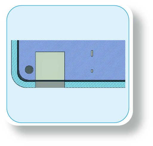
Bosses and holes
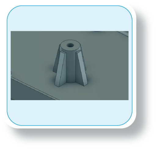
Screws are commonly used in enclosures and should be paired with bosses. Adding wide bosses around holes boosts strength and prevents bending.
If the screw might dig into the plastic, make the hole slightly smaller by 0.3mm. Also, ensure the bosses are as wide as the hole’s diameter, often used with ribs and gussets to prevent cracking.
Component clearance
A frequent challenge in enclosure design is components getting stuck. Different manufacturing methods have varying shrinkage and distortion rates, and machine tolerances can differ.
To prevent such problems, it’s advised to create 3D models of the components and include a safety margin considering machine tolerances. A typical 0.5mm gap between walls and components is a good initial step.
If you plan to prototype and produce internally, conducting tolerance tests with the equipment is recommended to ensure the enclosure functions correctly.
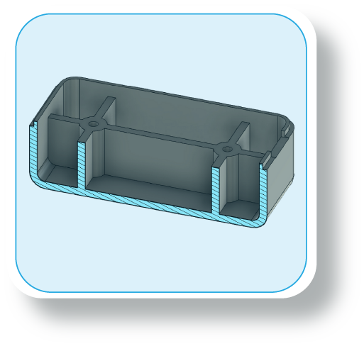
Port and hole clearance
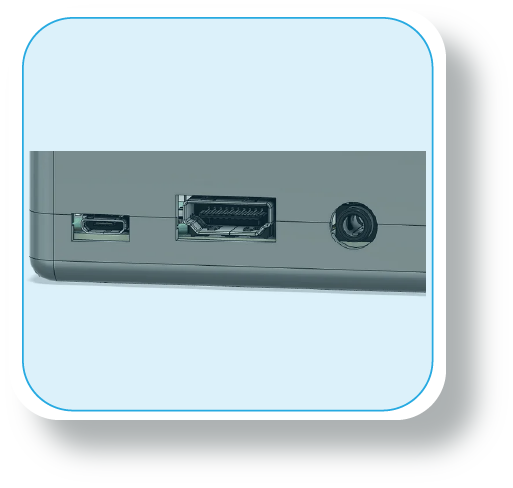
Clearance for ports and holes is crucial in design. The size and shape of the hole determine the clearance needed. For circular holes, it’s advisable to increase the diameter by 0.2-0.3mm. If precise alignment is essential, consider drilling the holes after manufacturing.
When it comes to port clearance, ensure the hole is correctly positioned and not too small to fit the connector easily. Add 1mm to each side of the hole and secure it firmly on the inside.
Design-assisted assembly
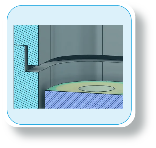
For enclosures with multiple parts needing exact alignment, adding a lip feature is essential. This can be incorporated into the design at any time and enhances the enclosure’s strength. When implementing the lip, account for the manufacturing method’s tolerance. Maintain a slight gap (0.5-1mm) between the lips for proper fit.
Cooling
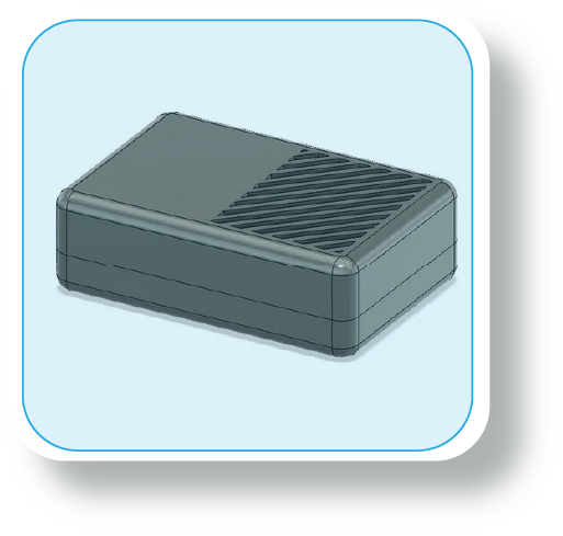
If any components heat up inside the enclosure, it’s recommended to incorporate ventilation features for optimal performance.
Ventilation cutouts are a popular choice and can be used with fans and heatsinks to improve airflow.
OUR KEY SERVICES
PLASTIC ENCLOSURE DESIGN
GigHz offers Customized Plastic injection Moulded Parts, Indoor and Outdoor Electronic Enclosure Design Services across various sectors, including Automotive Electronics, Consumer Electronics, IoT, Telecom, and Medical Products.
Our Offerings Include:
- Molding feasibility considerations during the design stage.
- Customized enclosure modifications as per customer specifications.
- Ensuring the balance of mass and rigidity.
SHEET METAL ENCLOSURE DESIGN
Our sheet metal enclosure designs turn flat sheets into 3D marvels, offering both protection and style for your electronic products.
Our Services Include:
- Support for metal fabricators and manufacturers in the design process.
- Efficient cooling design to enhance the performance of your electronic components.
- EMI shield is intricately shaped to match component tolerances and safeguard circuit components.
Why we Do? GigHz DNA

We challenge our MCAD Engineering capabilities with emerging technologies to keep your time and cost in control, thereby transforming product design with human touch quality.
Despite the challenges in technology, we stand out from the competition due to our innovative methods and value-driven process. This approach enables us to achieve a significant cost reduction of 52% while simultaneously increasing operational efficiency by 25%.
Conclusion
When designing an enclosure for electronic components in the aerospace industry, it’s important to consider the dimensions, materials, and design features carefully. Common enclosure materials like plastic parts can be 3D printed using processes such as SLA or MJF for scalability and customization.
Designing with features like snap fits, uniform wall thickness, and routing for internal components can improve thermal management and overall functionality. Enclosures with transparent lids for easy access to sensors or PCB assembly, as well as threaded fasteners for secure assembly, are also suitable for end-use products.
Additionally, considering factors like thermal resistance, external dimensions, and the need for off-the-shelf or custom enclosures is crucial in product development. Overall, designers need to think about the fusion of 3D printed parts with traditional manufacturing techniques to create a successful and functional enclosure.
To know more details, follow our founder through LinkedIn, https://www.linkedin.com/in/chandra-thimma/recent-activity/all/
Book a Free Consultation Call
Partner with Gighz and bring your most innovative design concepts to life. Our engineering cad services accelerate development so you can focus on your big vision.