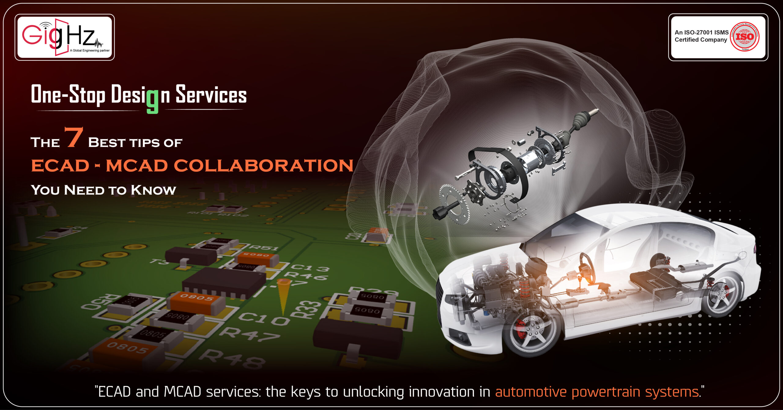
One-Stop Design Services: The 7 Best tips of ECAD-MCAD collaboration You Need to Know
Hey there!
Have you ever wondered how cars keep getting smarter and more reliable? Well, it’s all thanks to advancements in technology in the automotive industry!
And guess what?
Hey there!
Have you ever wondered how cars keep getting smarter and more reliable? Well, it’s all thanks to advancements in technology in the automotive industry!
And guess what?
Category :
Published Date :
February 9, 2024
Category :
Published Date :
February 9, 2024
Category :
Published Date :
February 9, 2024
We recently had an amazing opportunity to collaborate with a client in the automotive field.
They came to us for help in designing some seriously cool stuff: Our ECAD services-PCB design and MCAD services-enclosures for their powertrain systems.
Now, you might be wondering, what exactly are powertrain systems?
Well, think about the engine control units (ECUs) and transmission control modules that make your car go vroom and smoothly shift gears.
Yeah, those are the heroes we’re talking about!
Our client knew that these systems needed to be protected from environmental elements like moisture, dust, and vibrations.
After all, you don’t want anything messing with the operation of these critical components.
That’s where we came in!
Let’s get started!
Our journey of Printed Circuit Board(PCB) Design with ECAD-MCAD collaboration
Mastering the Art of Printed Circuit Board Design: The Perfect Blend of ECAD and MCAD
We embarked on a technical journey to design top-notch pcb designs and create sturdy enclosures, and conduct power integrity analysis.
Our goal was to make sure that these components were not only reliable but also performed at their absolute best with both electronic and mechanical.
When it came to high-speed PCB design process, we went all out to optimize the design.
We carefully crafted pcb layout circuit boards that were not only high-performance but also optimized for efficiency.
We design pcbs by considering things like power consumption, signal integrity, and thermal management.
But that’s not all.
We also focused on mechanical designing enclosures that could handle whatever Mother Nature decided to throw at them.
Moisture? No problem. Dust? Not a chance. Vibrations? Piece of cake!
We made sure these enclosures were built tough to protect those precious components inside.
How we did?
We’re going to explore how we approached each aspect to ensure optimal results from start to finish!
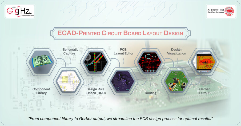
ECAD-Printed Circuit Board Layout Design
To design the PCB in Altium, we followed a systematic approach that maximizes efficiency and accuracy. Altium provides a comprehensive set of tools and features to streamline the design process. Here’s how we utilized Altium’s capabilities:
Component Library: Altium offers an extensive component library with a vast collection of pre-built components. We leveraged this library to quickly find and incorporate the necessary components into our design, saving time and ensuring accuracy.
Schematic Capture: Then the schematic capture module allowed us to create the circuit diagram using the components from the library. We connected the components properly, defined electrical parameters, and added any necessary annotations or notes to ensure clear communication of the design intent.
Design Rule Check (DRC): Altium’s DRC feature is a powerful tool that automatically checks the design against predefined rules and constraints. We configured the DRC settings to match our specific requirements, such as clearance between traces, minimum trace width, and spacing between pads. Running the DRC ensured that our design complied with industry standards and minimized the chances of errors or manufacturing issues.
PCB Layout Editor: By PCB layout editor, Altium provided an intuitive interface for designing the physical layout of the PCB. We transferred the connections and components from the schematic to the PCB layout, carefully arranging them to optimize signal flow, minimize noise, and ensure proper grounding.
Routing: Altium’s intelligent routing features made it easy to route traces efficiently. We manually routed critical signals to maintain signal integrity and used the autorouting functionality for less critical connections. Altium’s advanced routing algorithms ensured that the traces adhered to design constraints and avoided obstacles.
Design Visualization: Altium’s 3D visualization capabilities allowed us to view the PCB design in a realistic 3D representation. This feature helped us identify potential clearance and interference issues, especially when designing the enclosure for the PCB in Solidworks.
Gerber Output: Altium facilitated the generation of Gerber files, which are industry-standard files used for PCB manufacturing. We verified the Gerber output to ensure that it accurately represented our design and could be seamlessly translated into a physical PCB.
By utilizing Altium’s powerful tools and features, we were able to design a high-quality PCB that met our electrical requirements, adhered to design rules, and optimized performance. The combination of Altium’s robust functionality and our technical expertise allowed us to create a reliable and efficient PCB design.
ECAD-MCAD Design Collaboration
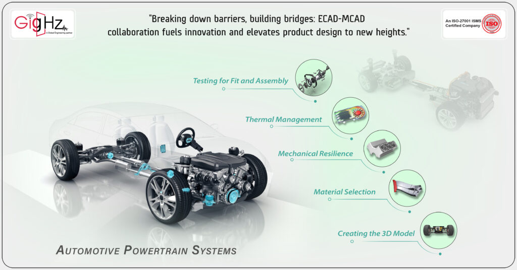
When it comes to designing enclosures for PCBs of collaboration between ECAD and MCAD in automotive powertrain systems, our approach focused on ensuring durability, mechanical resilience, and effective shielding. Here’s how we accomplished these objectives:
Solidworks is a powerful 3D CAD software that enables us to design enclosures with precision and functionality. Here’s how we utilize Solidworks for enclosure design:
Creating the 3D Model: Using Solidworks, we start by creating a 3D model of the enclosure. We take into consideration the dimensions, shape, and desired features of the enclosure. This includes factors such as mounting points, connectors, ventilation, and access points for maintenance or debugging.
Material Selection: Solidworks allows us to simulate different materials to determine their suitability for the enclosure. By considering factors such as strength, durability, and environmental resistance, we choose the most appropriate material for the specific application.
Mechanical Resilience: In Solidworks, we incorporate features to enhance the mechanical resilience of the enclosure. This includes adding structural reinforcements, ribs, and shock–absorbing mechanisms to protect the enclosed PCB from vibrations or impacts. We also perform stress analysis to ensure the structural integrity of the design under anticipated loads and forces.
Thermal Management: Solidworks enables us to simulate heat dissipation within the enclosure. By analyzing thermal pathways and conducting thermal simulations, we can optimize the design for efficient cooling. This may involve integrating heat sinks, fans, or other cooling mechanisms to maintain safe operating temperatures for the enclosed PCB.
Testing for Fit and Assembly: Solidworks allows us to evaluate the fit and assembly of the enclosure design virtually. We can simulate the installation of components, ensuring that everything fits properly and that there is adequate space for connectors, cables, and other necessary elements. This helps streamline the manufacturing and assembly process.
By leveraging the capabilities of Solidworks, we can design enclosures that are not only visually appealing but also functional, mechanically resilient, and thermally optimized. The software enables us to visualize the design, simulate performance, and refine the enclosure concept before moving to the manufacturing stage.
"One-Stop Design Services: The 7 Best tips of ECAD-MCAD collaboration You Need to Know"
Start early, save time:
Commence with a Unified Design Framework:
Create a unified design framework that encompasses both ECAD and MCAD requirements. Establish common file formats, design conventions, and communication protocols to ensure smooth data exchange between teams.
Implement a Concurrent Design Approach:
Adopt concurrent design methodologies where ECAD and MCAD teams work simultaneously rather than in isolation. Leverage collaborative tools and platforms that enable real-time synchronization, enhancing efficiency and reducing design iterations.
Utilize Intelligent Data Management Systems:
Implement intelligent data management systems that provide version control and revision history for ECAD and MCAD designs. This ensures traceability and facilitates effective collaboration while maintaining data integrity.
Enable Bi-Directional Data Exchange:
Leverage bi-directional data exchange capabilities between ECAD and MCAD software. Enable seamless transfer of design data such as component footprints, 3D models, and mechanical constraints to ensure accurate alignment between electrical and mechanical designs.
Perform Design Verification at Interface Level:
Conduct thorough design verification at the interface level to identify potential conflicts and ensure compatibility between the PCB layout and mechanical enclosure. Employ specialized tools for clash detection, clearance analysis, and thermal simulation.
Enforce Design Rules and Constraints:
Establish comprehensive design rules and constraints in both ECAD and MCAD environments. This includes electrical rules like signal integrity and EMI considerations, as well as mechanical rules such as clearance requirements and tolerance limits.
Implement Design Automation and Simulation:
Leverage automation tools and simulations to streamline the ECAD-MCAD collaboration process. Perform automated checks for design rule compliance, simulate mechanical stress analysis, and optimize thermal management for enhanced reliability and performance.
Our Notable Upgrade: Engineering as a Service (EaaS)
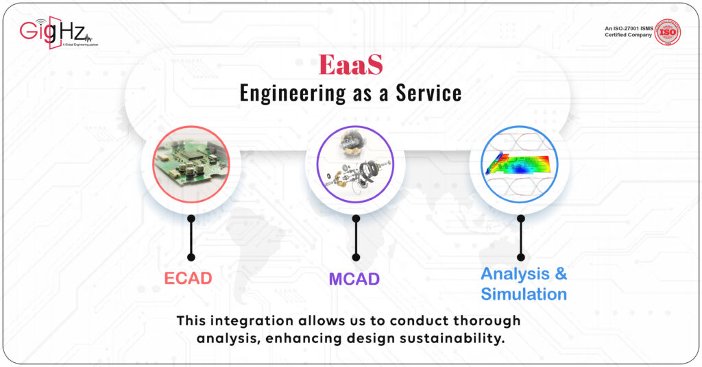
You know, as the need for advanced and integrated engineering solutions keeps soaring, our Engineering as a Service (EaaS) are really stepping up the game.
We’re harnessing the power of ECAD, MCAD, and Analysis & Simulation. This gives us a great position to be frontrunners in this industry.
What’s really cool is that we offer a full package covering every single step of the engineering process.
And honestly, it’s this kind of approach that’s going to shape the future of our engineering.
It’s exciting stuff!
Why we do?
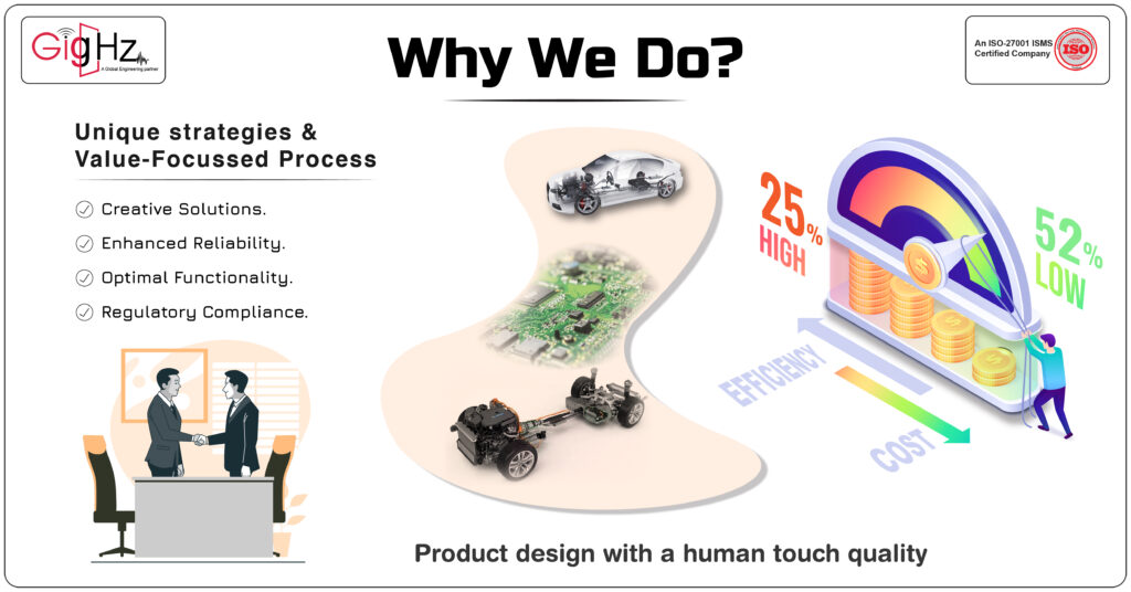
Our motivation stems from the intricate nature of the ECAD-MCAD collaboration with Analysis & Simulation extending from our capabilities to Automotive Industry.
Despite these complexities, we distinguish ourselves by implementing unique strategies and a value-focused process.
This differentiated methodology results in a remarkable reduction in costs by 52%, while concurrently enhancing operational efficiency by 25%.
Conclusion
In conclusion, successful ECAD-MCAD collaboration is crucial for efficient and accurate product design. By following best practices such as utilizing co-design approaches, implementing intelligent data management systems, and leveraging automation tools, teams can seamlessly integrate their electrical and mechanical designs.
Asking the right questions, embracing 3D visualization, and enforcing design rules further enhance collaboration. With these tips, businesses can optimize the collaboration process, reduce iterations, and deliver superior products to market.
“Ready to take your design projects to the next level? Discover our Specialities. Visit our Services Page. https://gighz.net/services/
Schedule a Call. Book a free consultation now.https://calendly.com/gighz/30min