How Mechanical Robotic Arm Are Transforming Industries?
Hey there! Ever seen a robot arm? It’s like a mechanical version of a human arm. It can do lots of cool stuff like welding, putting things together, painting, and picking up objects. Tap around to see all the different jobs these robot arms can do. They’re super speedy, really accurate, and they’re great at doing the same thing over and over perfectly
Meet the challenging partner of modern cars – the ECU in ADAS! You can call it the ‘smart controller.’ It’s like the boss of all the information from sensors, helping your car stay safe and work better. This little brain acts as a super-smart traffic helper, listening to signals from all over the car.
Category :
Published Date :
December 22, 2023
Category :
Published Date :
December 22, 2023
Category :
Published Date :
December 22, 2023
The way these arms move depends on how many joints they have. More joints mean they can move in more ways. That’s what lets them do all sorts of tasks in factories and other places.
They’re used for making things faster and better in factories!
You can even play with how the arm moves using the buttons at the bottom. Try changing how fast it moves or where it goes.
Got any questions or want to see something specific? Just ask!
These robot arms are the future of making stuff, making things quicker and more accurate than ever!
Go through our project where we effectively used MCAD for designing Robotic arm, an essential tool in this modern era.
The Challenges in Our Project
Transforming a product involves complex steps like scanning its details, crafting a precise 3D model, and reworking its components.
Creating manufacturing plans for these modifications adds certain layers of challenges. Some of the highlights of the challenges that we faced are given below.
- Capturing data from the original product might be tricky due to its shape and surfaces, needing a really accurate scanning method.
- Making a complete 3D model of the whole product is tough. It means getting every tiny detail right to match the real thing.
- Changing the base support and arms means making tricky adjustments without messing up how the product works.
Drawing out detailed plans for how to make the changed product needs a good grasp of how things are built and exact instructions for the manufacturers
The Reverse Engineering Process
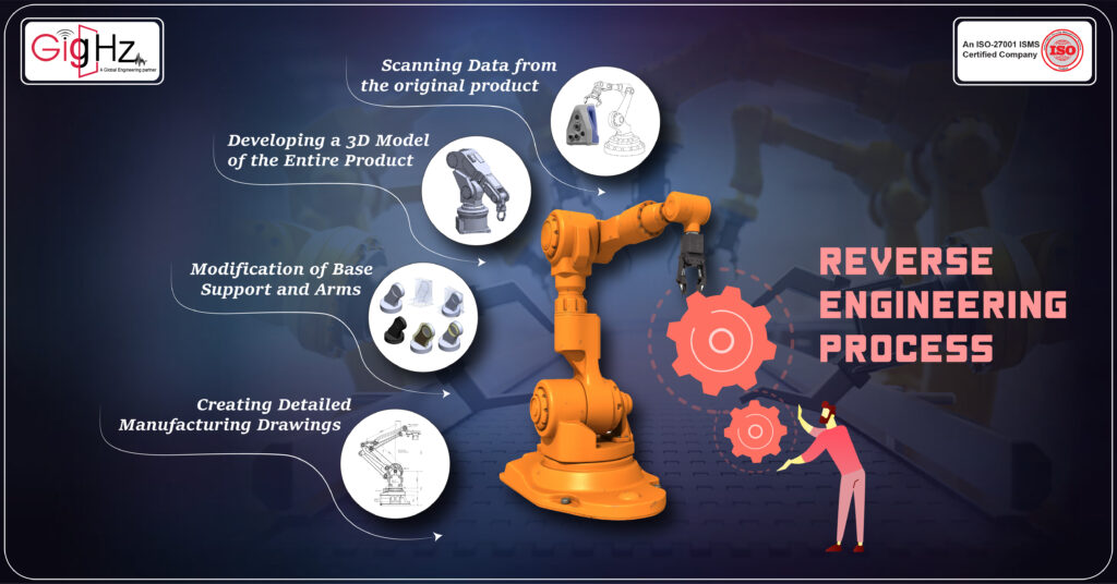
Reverse engineering is the process of analyzing a system or a product to understand how it works and how it was designed. It is used to recreate the product without the original design files.
A robotic arm is a type of mechanical device that can perform tasks that require speed, precise movements, and high accuracy.
We took up these two core areas and combine it to design an innovative and beneficiary final end product.
The project work flow is a step-by-step process that starts with scanning and end up with manufacturing drawings.
- Scanning Data from the Original Product:
The initial task revolved around capturing detailed information from the original product using advanced scanning techniques. This involved employing technologies to meticulously record intricate dimensions, features, and structure to ensure an accurate representation.
- Developing a 3D Model of the Entire Product:
Creating a comprehensive digital replica of the complete product was a crucial step. Using the data acquired from scanning, a detailed and accurate three-dimensional model was constructed to replicate the physical product virtually.
- Modification of Base Support and Arms:
Focusing on enhancing performance and functionality, adjustments were made to the base support and arms of the product. This step involved meticulous tweaking and improvements to elevate the product’s capabilities.
The modifications should be perfectly aligned with client’s needs. While implementing, the major changes have to ensure that the final product must get aligned with client’s requirements and expectations.
- Creating Detailed Manufacturing Drawings:
To facilitate practical implementation, detailed manufacturing drawings were crafted. These drawings served as comprehensive blueprints, providing precise instructions and specifications for the fabrication of the modified design.
The Project Execution

In this project, we aimed to revamp the existing product’s design, injecting novelty and interest. Our expertise in CAD and reverse engineering empowered us to reimagine the design with innovative modifications to transform it into improved and captivating final product.
Utilizing the (Artec Eva Lite) scanner, the project initiated by meticulously scanning each part of the original product. The aim was to gather detailed data while ensuring each part’s distinctiveness, ultimately culminating in a final product replica that mirrored the original in every aspect.
Further, minor modifications were introduced to the 3D model by creating specific configurations for each individual part. This step aimed to enhance the overall functionality while preserving the product’s original design integrity.
The base support underwent a transformation from a single-sided to a double-sided. This change aimed to enhance stability and reinforce the foundational structure, ensuring improved balance and support for the entire system.
Moreover, design alterations were implemented for both Arm1 and Arm2, deviating from the original base structure. These changes were made to refine their functionalities and align them more effectively with the updated base support.
The adjustments optimized the arm’s performance, considering factors such as increased load-bearing capacity, enhanced manoeuvrability, or improved attachment mechanisms.
The Geomagic in SolidWorks were employed for the design phase, facilitating the precise manipulation and configuration of the 3D models. This software combination offered the versatility required to modify and fine-tune each part according to the project requirements.
Ultimately, two output models were developed: one reflecting the original product’s design with detailed modifications, and the other aligning closely with the modified configurations. These models served as the final representations of the enhanced product.
Additionally, as part of the project deliverables, comprehensive manufacturing drawing files were provided. These detailed files contained essential instructions and specifications necessary for fabricating the modified design, ensuring accuracy and precision in the manufacturing process.
The Design Steps
To implement modifications, a systematic approach was adopted, introducing specific changes to each part of the original design.
Creation of Variables
The initial step involved defining and establishing variables within the design framework. These variables allowed for dynamic adjustments and parameterization, enabling swift and precise alterations across the design.
Configuration Development
Creating configurations for each part was pivotal in tailoring variations within the design. This step facilitated the ability to modify and adapt specific aspects of the parts, ensuring flexibility and versatility in the final product.
Feature Manipulation – Suppressing and Unsuppressing
The process involved strategic manipulation of features within the design. By selectively suppressing and unsuppressing features, the aim was to optimize efficiency and reduce overall work time. This method allowed for quicker adjustments while maintaining design integrity.
The design changes were systematically executed by introducing variables for dynamic adjustments, creating configurations for part variations, and strategically manipulating features through suppression and unsuppression. These steps ensured adaptability, efficiency, and precision throughout the modification process.
Engineering as a Service
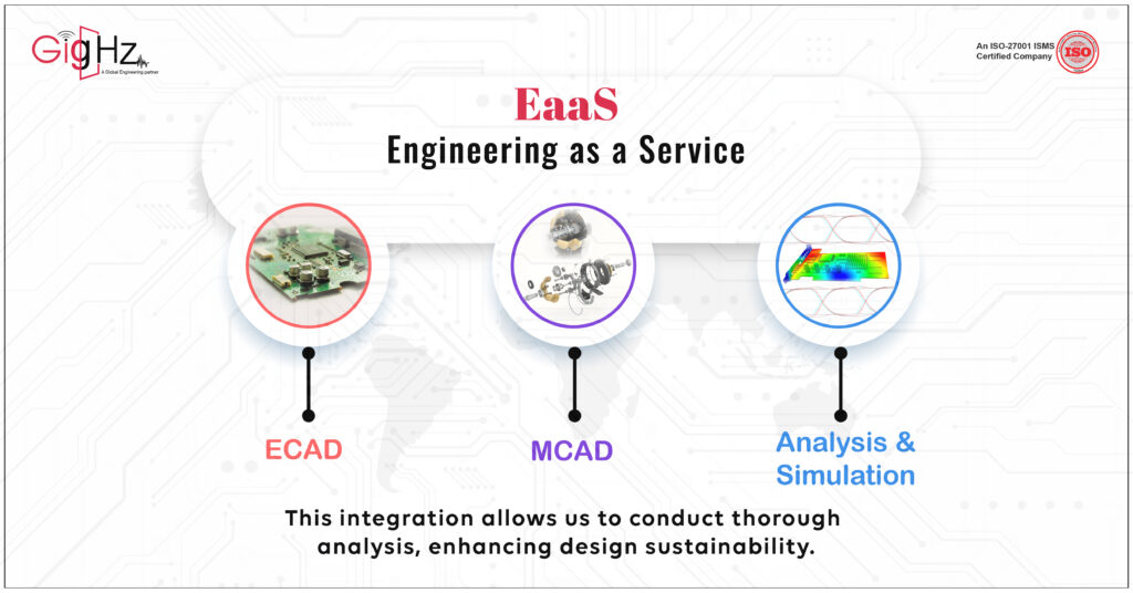
At the core of our electronics specialization lies the integration of ECAD (Electronic Computer-Aided Design), MCAD (Mechanical Computer-Aided Design), and Analysis & Simulation.
This integration is designed to streamline design, production, and operational workflows, ensuring efficiency at every stage.
By merging these disciplines, we conduct thorough analyses that strengthen the robustness of our designs while fostering inventive solutions.
This approach consistently delivers high-quality results cost-effectively, even within stringent timelines, driving innovation and durability hand in hand.
Why We Do?
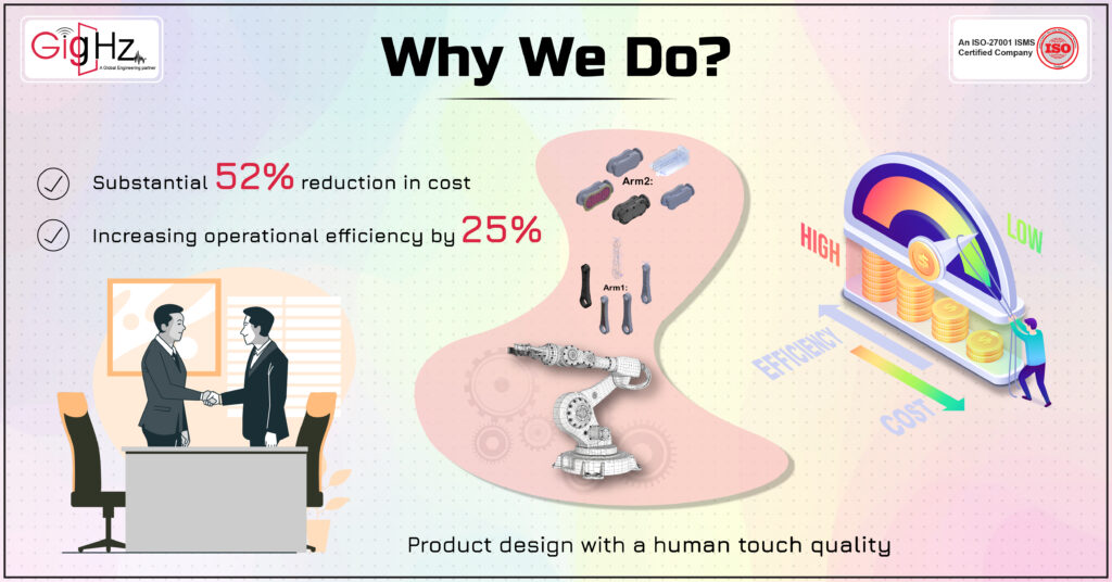
Diving into the complexities of MCAD design for robotic arms sparks our drive. Despite these detailed challenges, our standout quality arises from using innovative methods strategically and focusing on value-centered processes.
This unique mix helps us achieve impressive outcomes—a remarkable 52% cut in costs while boosting operational efficiency by 25%.
Our approach not only handles these complexities but also brings noticeable improvements, setting new standards for efficiency and cost-effectiveness in robotic arm design.
Conclusion
Throughout this project, our focus centered on amplifying the appeal of the existing product’s design.
Utilizing our CAD expertise and proficiency in reverse engineering, we adeptly navigated challenges, culminating in significant enhancements.
Our precise recreation of the 3D model and strategic modifications tailored the product ideal for industrial applications.
Ready to elevate your product designs?
Connect with us today and discover how our expertise can transform and optimize your projects for superior performance and functionality.
Book a demo call nowhttps://calendly.com/gighz/30min