Zonal and Body Domain Controller Explained
In the dynamic world of automotive technology, traditional domain architectures are making way for innovative zonal architectures. Unlike grouping vehicle systems based on function, zonal architectures organize functions into distinct physical zones within the vehicle. This approach offers enhanced efficiency and enables software-defined vehicle architectures to deliver flexibility, scalability, compatibility, and upgradability across different hardware components while fulfilling critical technical and safety requirements.
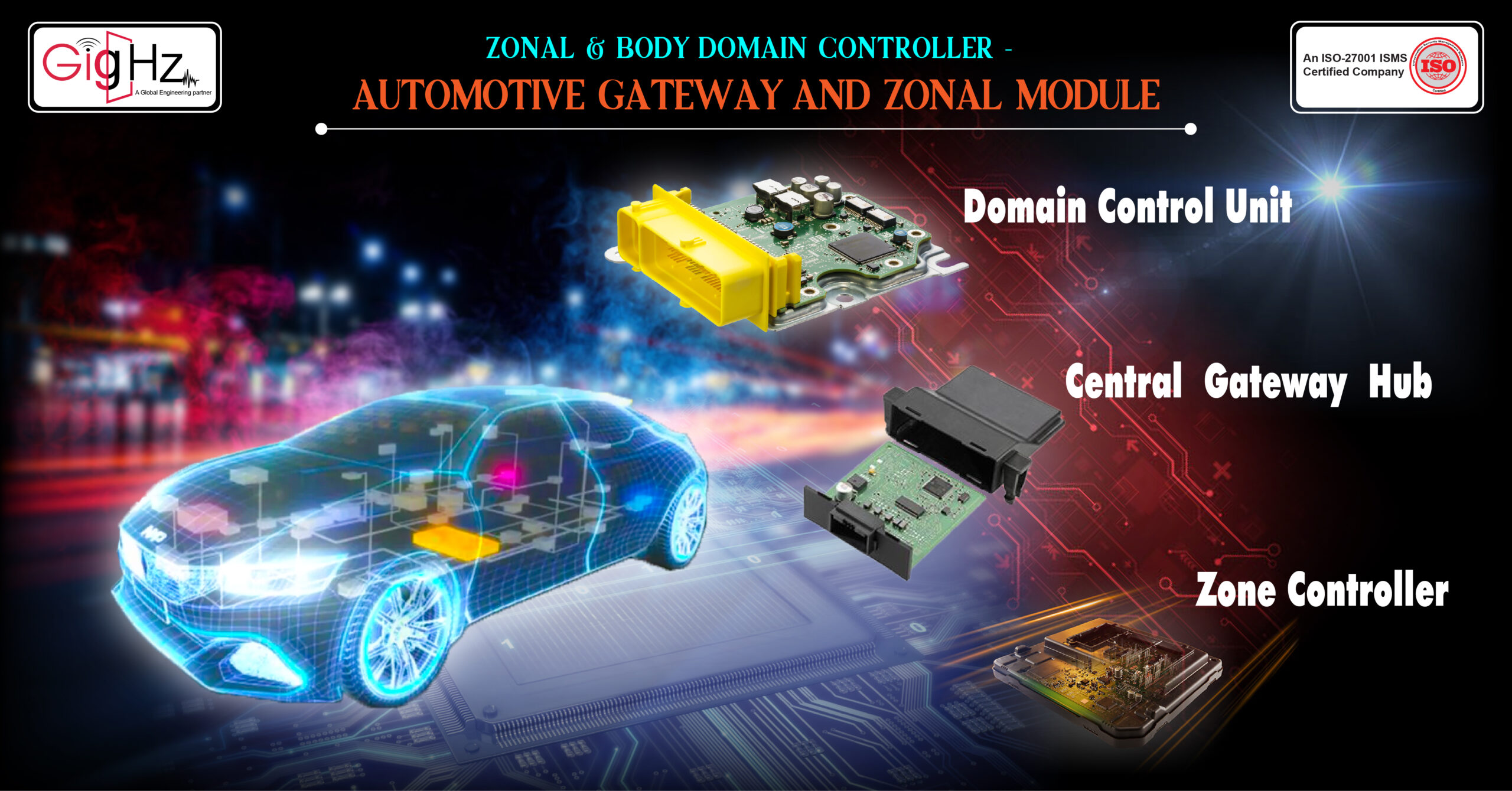
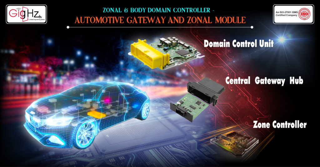
In this article, we delve into the concepts of zonal and domain controllers, shedding light on their significance in modern automotive design. We will specifically focus on the Automotive Gateway and the zonal module of the zonal and body domain controller, exploring their roles and benefits in this evolving landscape.
Effective Communication Through Automotive Gateway
Lorem ipsum dolor sit amet, consectetur adipiscing elit. Sed laoreet tortor non neque volutpat tempor. Maecenas convallis justo euismod, accumsan eros feugiat, tincidunt mauris. Nulla sapien quam, ornare nec finibus et, venenatis ut arcu. Sed et erat sed dui fermentum venenatis sit amet venenatis lectus. Vestibulum ultricies malesuada massa sodales finibus. Vestibulum sodales orci eu pellentesque lobortis. Nulla ac congue ipsum.
Category :
Published Date :
October 25, 2023
Category :
Published Date :
October 25, 2023
Category :
Published Date :
October 25, 2023
What is a Domain Controller?
Today, every electronic control system in the car, such as Instrument Cluster, Infotainment, Anti-lock braking system, Engine Management System, Transmission Control Unit, and Body Control Management is a self-sufficient unit with its own sources like ROM, RAM memory, microprocessor or microcontroller, I/O and power supply.The idea of primary domain controller is to replace multiple distributed ECUs with a single powerful central computer with multi-core. Multi-core processing technologies integrate multiple ECUs into one single chip. In a multi-core solution, these individual ECUs retain separated and independent processing space.
However, a lot of redundant components like housing, drivers, wire and harnesses, and power supplies can be eliminated. These not only largely save cost but also the component’s weight and space.
Moreover, communication between ECUs is within the processor itself instead of communicating over an external network like CAN or LIN, this will reduce the data latency and system complexity considerably.
Effective Communication Through Automotive Gateway
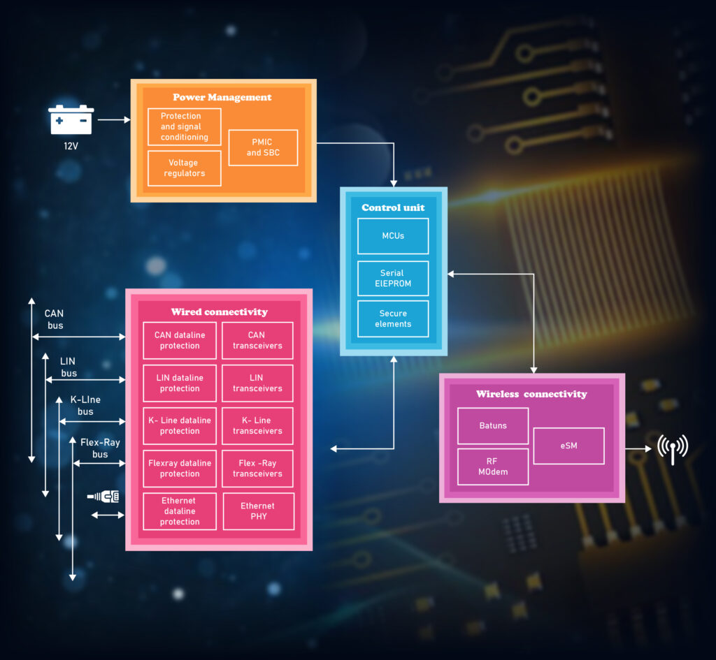
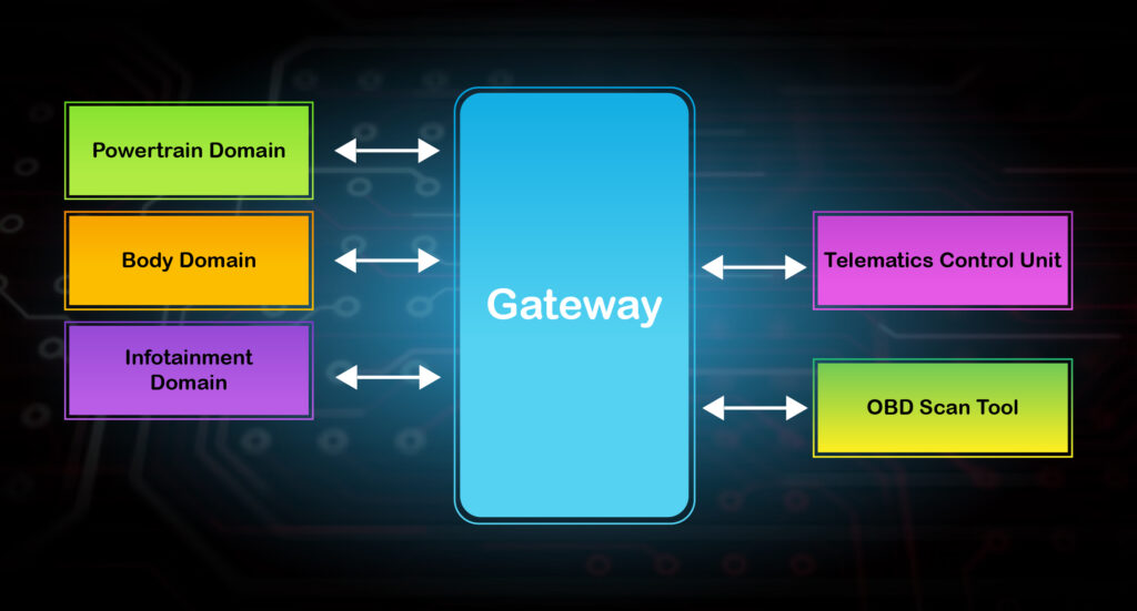
A gateway is a central hub that securely and reliably interconnects and transfers data across the many different networks found in vehicles.It provides physical isolation and protocol translation to route signals between functional domains (powertrain, chassis and safety, body control, infotainment, telematics, ADAS) that share data.
Vehicles are increasingly dependent on electronic control units (ECU) to manage the advanced features that enhance the driving experience.The gateway controller plays a fundamental role as a communication bridge between the various ECU networks used by these different applications, managing the exchange of data with external interfaces including CAN (low, high speed), LIN, ISO-9141, Flex Ray, and Ethernet protocols.
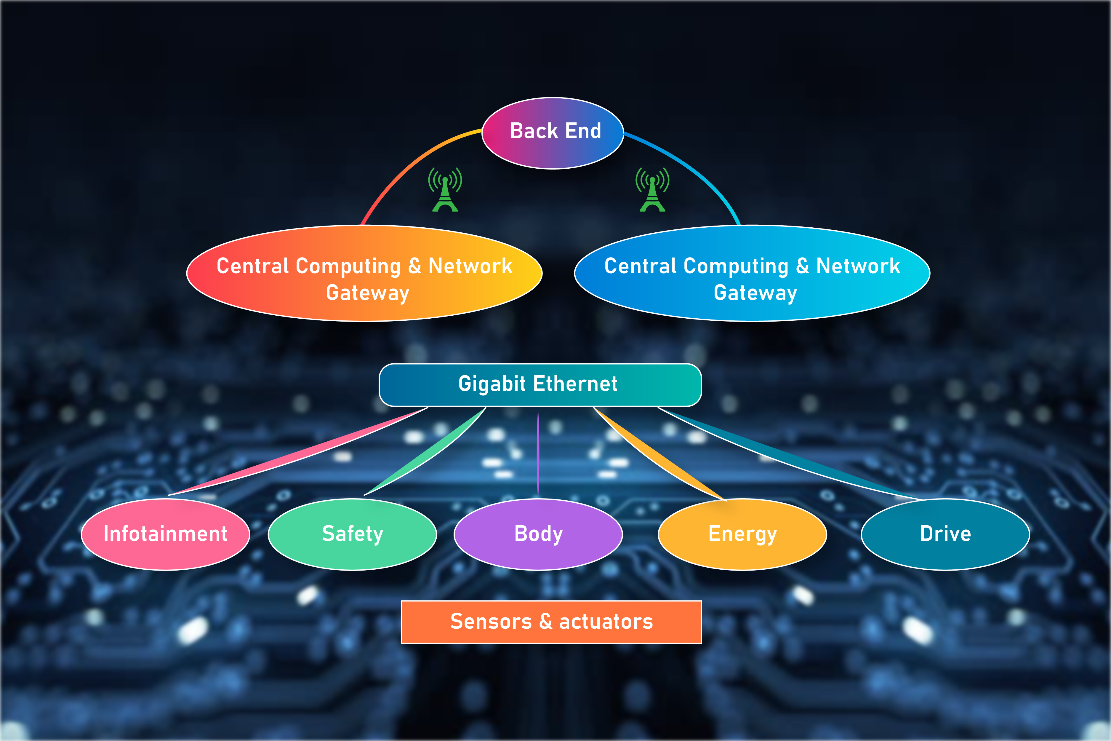
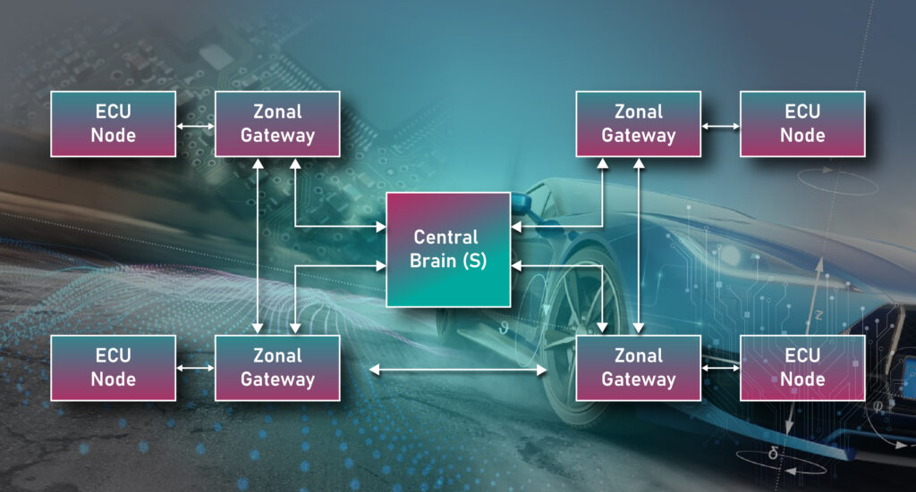
Zonal architectures enable efficient power and data distribution around the vehicle, while improving wire cost, weight, and manufacturing.
Where individual functions or functional areas were previously integrated into the vehicle in individual control units, new thinking is now being applied.
The new Zone Control Units consolidate vehicle functions in physical zones close to the sensors and actuators and form the middle layer between the server level of the HPCs and the individual sensors and actuators “on site“. This ensures intelligent task distribution between all levels.
A key component in this architecture is the zone controller, it is responsible for connecting the high number of actuators and sensors to a central compute ECU and, depending on application distribution, can have a significant role in strategy within a zone.
This evolution can come via logical distribution of functions onto less diverse software/hardware platforms, and through physical changes to a zonal-based network.
Body Control Module
The Body Control Module (BCM) is an electronic control unit (ECU) in a vehicle that is responsible for managing and controlling various electrical and electronic systems related to the body of the vehicle. It serves as a central hub for communication and coordination between different body-related components and subsystems.
The BCM is typically located in the interior of the vehicle, often in the vicinity of the dashboard or under the seats. It is connected to numerous sensors, switches, and actuators throughout the vehicle’s body, such as door locks, windows, lighting systems, wipers, horn, climate control, seat controls, and more.
The primary function of the BCM is to receive input signals from various switches and sensors, interpret those signals, and then send appropriate commands to the corresponding actuators or subsystems to perform the desired actions. For example, when the driver presses the window switch, the BCM receives the input signal, processes it, and activates the window motor to open or close the window accordingly.
Additionally, the BCM may also handle security functions, such as anti-theft systems and keyless entry systems. It manages the communication between the vehicle’s key fob and the locking/unlocking mechanisms.
Difference between Domain Controller and Body Control Module
The Body Control Module (BCM), , is responsible for managing and controlling various electrical and electronic systems related to the body of the vehicle. It primarily focuses on body-related functions such as lighting, climate control, door locks, windows, and other similar features. The BCM is typically located in the interior of the vehicle and communicates with various sensors, switches, and actuators within the body of the vehicle.
On the other hand, a Domain Controller is a more advanced concept in automotive electronics. It consolidates the control of multiple ECUs, often within a specific domain or functional area, into a single centralized computing unit. A Domain Controller replaces multiple distributed ECUs with a powerful central computer, integrating and coordinating the functions of those individual ECUs.
The Domain Controller architecture is designed to handle complex systems and functions within a specific domain, such as powertrain, chassis, body control, or infotainment. It enables efficient communication and data exchange between different components and subsystems within that domain, improving system integration, reducing wiring complexity, and enhancing overall performance.
While a Body Control Module (BCM) is a specific ECU focused on body-related functions, a Domain Controller is a more comprehensive concept that encompasses the integration and control of multiple ECUs within a specific domain.
Design of PCBs
PCB design is an intricate process requiring careful consideration of a variety of factors and attention to the tiniest details.
Fail to pay attention to these minute details, and you may end up tossing aside weeks of work to start anew when you realize that your failure to account for a material consideration or a functional requirement makes your current design unworkable.
The first step in any complex process is often one of the most crucial, and the same holds true for PCB design. That’s why they say that failing to plan is planning to fail.
The PCB is a pre-configured wired card that enables signals and power to flow between electronic parts and devices.
The PCB holds everything together, connects all the circuits, and provides the functional reliability we expect in purpose-driven smart devices during repeat usage.
The single most important first step in the PCB design process is Ideation, Definition, and Validation – all before starting a design and/or prototype.
With scope clearly defined, the Design and Prototype process can begin.
Need For SI/PI Analysis in High-Speed PCB Design
Signal Integrity (SI) signifies the signal’s ability to propagate without distortion. Signal integrity is nothing but the quality of the signal passing through a transmission line.It gives the measurement of the amount of signal degradation when the signal travels from the driver to the receiver. It also refers to the challenges posed by ensuring that wires carry correct, uncorrupted values.
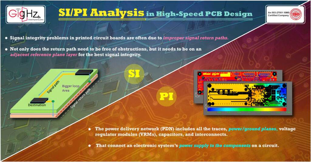
We moved to digital circuits in large part to minimize the effect of corrupted signals in analog circuits. But digital circuits are also susceptible to noise.Signal integrity problems in printed circuit boards are often due to improper signal return paths. Not only does the return path need to be free of obstructions, but it needs to be on an adjacent reference plane layer for the best signal integrity.
Discontinuities, including irregular impedance or sharp bends, in addition to other things, can affect the integrity of signals in digital devices. In such events, a circuit becomes unstable, unreliable and in some instances even inoperable.Signal integrity for high-speed PCB designs is important for ensuring data can be passed between components on a PCB and to ensure signals can be interpreted by a receiver component.
The quality of a signal is determined by the trace on a printed circuit board. If the impedance of a trace line isn’t uniform, signal distortion will occur. This can be prevented by utilizing consistent spacing and length matching for differential pairs.
There is also the matter of best PCB layout practices to ensure low EMI emission from a PCB. Good power integrity in a circuit board means that its power delivery network is designed to provide stable voltage references and to distribute power to all of the board components within acceptable noise and tolerance levels.The power delivery networks (PDNs) of circuit boards have to be carefully managed to provide clean power across the PCB to all of its components.
A board that hasn’t been designed for good power integrity can exhibit a lot of problems, such as power ripples that create crosstalk in the high-speed circuits of the board.Excessive noise in a PDN will affect the voltage levels required by components, and if they drop below the acceptable level, the associated circuits may malfunction.
Even if the voltages are within the tolerance required by the part, the noise on the PDN may appear as crosstalk on signals, causing those signals to be misinterpreted.PDN noise has the potential of radiating EMI through the planes and connections of the power delivery network.Obviously, good power integrity in PCB design is essential to the success of the design.
Conclusion
Zonal modules and connections in physical areas of the vehicle transfer most of processing power in a central vehicle computer.
The way it realizes its function is given by a set of basic architecture parameters and modules.
It will provide many benefits as it reduces wiring cost and weight, and provides a scalable and centralized software.
This article explains the design and implementation of zonal modules and automotive gateway.
To know more, please reach us @ info@gighz.net