PCB Library
When I hear “PCB library,” I immediately think of a collection of essential components and footprints that are integral to designing and assembling printed circuit boards (PCBs). It’s not about educational materials, but rather a carefully curated set of designs that ensure the components fit together correctly and perform reliably.
A top-quality PCB library isn’t just a set of random pad layouts. It follows strict standards for consistency, accuracy, and compliance, making sure every component in the library has been properly defined and tested for use in real-world applications. This ensures designers don’t just save time, but also avoid costly mistakes in the production process. What’s your experience with PCB libraries?
Building a standard PCB library can be tough. It’s not just about starting it;
Keeping it up to date is crucial too.
A PCB library is like a treasure chest full of important building blocks for creating electronic circuits on circuit boards.
Inside, you’ll find symbols representing different parts, footprints showing how they physically fit on the board, and details like part numbers and specifications.
It’s like having a map that guides you on where to place each component for a successful circuit design.
This resource also includes additional information crucial for manufacturing, such as datasheets, suppliers, and component behaviors for ensuring everything works smoothly together.
For your good understanding, we share our experience of designing the pcb library, what we have done for our Automotive rearview camera mirror board
Enjoy your Reading!
Creating a New PCB Library using Software Tools
In Altium Designer, the first step in creating a new PCB library is to select the footprint library option from the main menus.
This will open a dialog where you can define the footprint editor template and destination for the new library.
Once this is done, you can generate the pcb library file with the footprints list from the technical datasheet of the electronic component.
Next, you can model the component footprints in the 3D view, using the 3D models from the vendor’s MCAD software.
Before exit from the editor, make sure to verify that all footprints are IPC compliant and without any error.
Once the footprint library is created, you can copy the design data to an integrated library and define the schematic symbol for the electronic component. In the schematic section, you can configure the parameters and drop-down lists for the component.
When you click OK, the component library will be automatically updated with the new data.
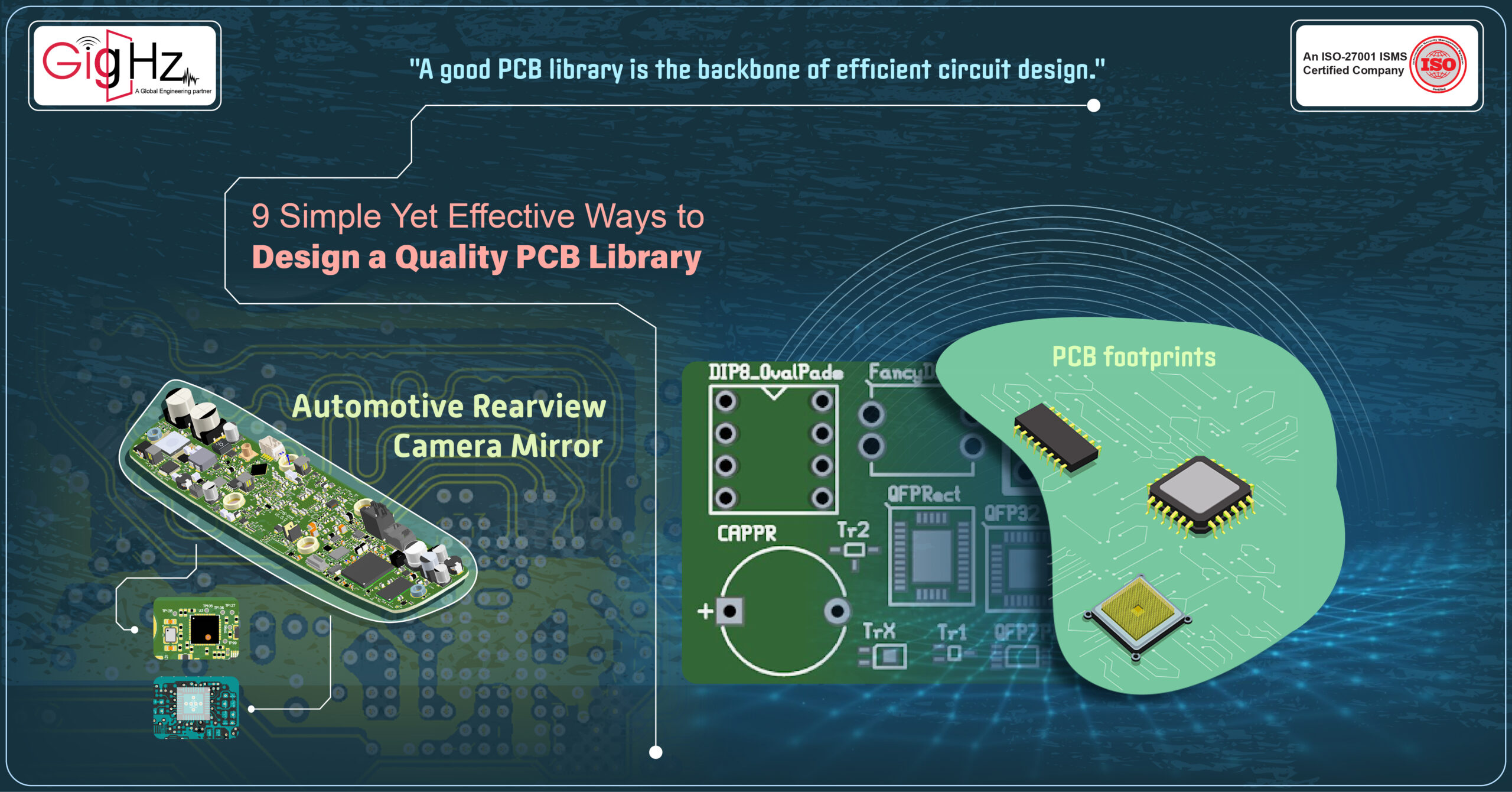
In the PCB design space, you can enable the display of the active PCB library and click on the component to edit its description or model.
The software also allows you to configure the layers, dimensions, and pins of the component before placing it on the panel.
Finally, you can create the library.
Standardization made simple!
Creating a PCB library for the rearview camera mirror in automobiles involves designing and compiling components specific to this application.
Here’s a breakdown of the steps involved in PCB library creation for the rearview camera mirror:
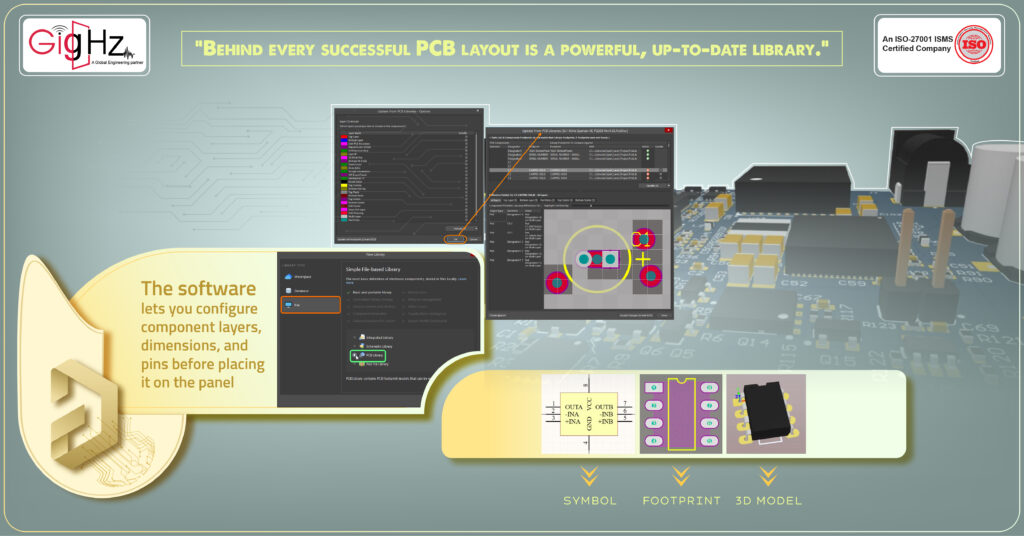
- Camera Module Component: Designing a specific component for the camera module used in the rearview camera system. This includes the image sensor, lens, and supporting circuitry.
- Display Interface Components: Including components for the display interface, such as connectors, display driver ICs, and interface protocols like HDMI or LVDS.
- Power Management Components: Adding power management components like voltage regulators, filters, and protection circuits to ensure stable power supply to the camera and display.
- Signal Processing Components: Incorporating components for signal processing, such as amplifiers, ADCs, and image processing ICs to enhance the quality of video signals.
- Communication Interfaces: Integrating communication components like CAN bus transceivers or Ethernet controllers for data transmission between the rearview camera system and other vehicle systems.
- Mounting and Connection Components: Including mounting holes, pads, and connectors tailored for the rearview camera mirror assembly to ensure proper mechanical and electrical integration.
- Environmental Considerations: Ensuring that components are selected or designed to withstand automotive environmental conditions like temperature variations, vibrations, and EMI/EMC requirements.
By systematically designing and compiling these components into a dedicated PCB library, engineers can streamline the PCB layout process for rearview camera mirrors in automobiles, facilitating efficient design, testing, and production of automotive electronic systems.
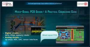
9 Simple Yet Effective Ways to Design a Quality PCB Library
Here are the steps tailored specifically for designing a PCB library for the rearview camera mirror in automobiles:
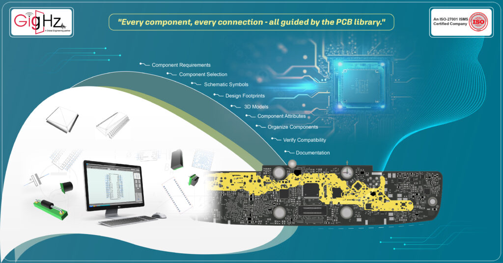
- Identify Component Requirements:
List the necessary components for the rearview camera mirror system, such as the camera module, display interface components, power management elements, signal processing components, communication interfaces, and mounting/connection components like we have listed above.
- Component Selection or Creation:
Choose suitable components from verified sources or create custom components that align with automotive standards and the specific requirements of the rearview camera mirror application.
- Create Schematic Symbols:
Develop clear and accurate schematic symbols for each component to ensure easy identification and placement in the schematic design phase.
- Design Footprints:
Generate precise footprints for each component based on package dimensions, pin configurations, and mechanical considerations to guarantee proper soldering and assembly on the PCB.
- Assign 3D Models (if applicable):
Assign 3D models to components that require visual representation to aid in visualizing component placements, clearances, and potential interferences within the PCB layout.
- Set Up Component Attributes:
Define essential attributes like part numbers, descriptions, datasheet links, and manufacturer details to provide comprehensive information about each component in the library.
Organize Components into Categories:
Categorize components according to functionality or type to streamline access and selection during the PCB layout process, ensuring efficient placement and connection of components.
Verify Compatibility and Standards Compliance:
Validate that all components meet automotive industry standards, environmental requirements, and specifications essential for seamless integration into the rearview camera mirror system.
Documentation and Maintenance:
Document detailed information for each component, including specifications, design notes, and usage guidelines. Regularly update and maintain the library to incorporate any new components or revisions based on ongoing design improvements.
By following these tailored steps, you can effectively design a specialized PCB library for the rearview camera mirror in automobiles, streamlining the design process and ensuring the reliability and functionality of the PCB layout for this critical automotive application.
Happy Designing!
Our PCB Library Creation Services
- GigHz streamlines schematic part creation with integrated solutions for symbol and footprint development.
- GigHz offers meticulously crafted PCB footprints adhering to IPC-7351B standards for optimal layouts.
- GigHz ensures library verifications meet stringent standards for component integrity.
- GigHz excels in PCB library development following industry best practices and tool integration.
- GigHz provides continuous maintenance to update and expand libraries with new components.
Conclusion
In conclusion, the usage of the PCBLib Wizard in CAD software has become essential for users in the librarian field.
With features like being able to check the density of footprints, preview their graphic size, and choose a default format, the wizard has made creating new footprints much easier and efficient.
It also helps prevent inadvertent mistakes by guiding users through the process step by step. Nowadays, the wizard has become a go-to tool for library creators to quickly add new footprints to their database.
By clicking just, a button or a tab, users can access a wide range of options and streamline their workflow.
Additionally, the wizard now includes features for selecting footprints from a particular vendor, making it even easier for users to find the right component for their project.
Discover our Specialities. Visit our Services Page. https://gighz.net/pcb-library-creation-services/
#pcblibrarydesign #qualitypcb #electronicdesign #componentintegration #schematicsymbols #footprintcreation #ipc7351bstandard
Stuck in a loop of challenges? Always pick smart solution that works
What’s your biggest challenge when migrating PCB designs between tools?
What’s your go-to solution for speeding up PCB tool migration?
Please answer both poll questions before submitting.
Thank you for your response! 😊
9 Simple Yet Effective Ways to Design a Quality PCB Library
Book a Free Consultation Call
Partner with GigHz and turn your most innovative design concepts into reality. Our engineering CAD services streamline the development process, helping you bring ideas to life faster and more efficiently. This allows you to focus on what matters most—your big vision. Let’s make it happen together!
Related Blogs