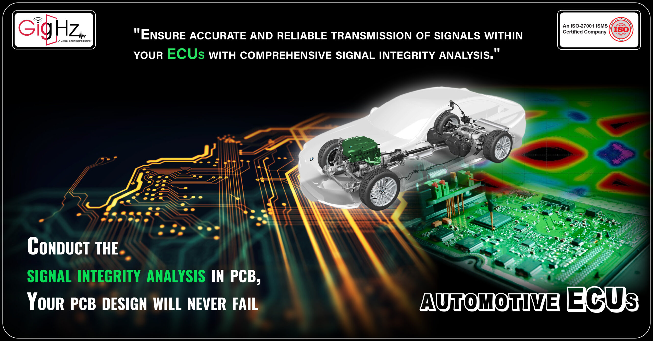
“Conduct the Signal Integrity analysis in PCB, your PCB design will never fail.”
Welcome to our latest blog update!
Hey there!
Today, we’ll explore what exactly signal integrity analysis in PCB entails, how we go about conducting it, and why it plays a vital role in ensuring optimal functionality of ECUs.
Welcome to our latest blog update!
Hey there!
Today, we’ll explore what exactly signal integrity analysis in PCB entails, how we go about conducting it, and why it plays a vital role in ensuring optimal functionality of ECUs.
Category :
Published Date :
February 13, 2024
Category :
Published Date :
February 13, 2024
Category :
Published Date :
February 13, 2024
In the fast-paced automotive industry, staying ahead of the competition requires continuous innovation and improvement.
As technology advances, the complexity of automotive ECUs increases, and with that comes the need for thorough signal integrity analysis in printed circuit board design.
One key point to note is that our client has specifically requested us to conduct signal integrity analysis for their automotive ECU PCB circuit board design which was designed by us.
They understand the importance of ensuring reliable communication within the ECU and want to optimize the performance and functionality of their electronic systems.
By conducting signal integrity analysis, we can identify potential issues that could affect the quality and reliability of electrical signals within the ECU.
This analysis involves techniques such as pre-layout design space exploration and post-layout verification to catch design errors and optimize signal characteristics of signal integrity simulation.
Our goal is to ensure that the signals transmitted within the ECU are accurate, without any signal integrity problems such as signal degradation, signal distortion, crosstalk, impedance mismatching or interference.
Let’s dive into the fascinating world of signal integrity analysis in automotive Electronic Control Unit (ECU) PCB design.
Today, we’ll explore what exactly signal integrity analysis entails, how we go about conducting it, and why it plays a vital role in ensuring optimal functionality of ECUs.
"Ensuring Smooth Signal Travel: A Journey through PCB Layout with Signal Integrity Analysis"
Understanding Signal Integrity Analysis
Signal integrity analysis refers to the process of assessing and optimizing the quality and reliability of electrical signals within a high-speed PCB design.
For automotive ECUs, which are responsible for controlling critical functions in vehicles, such as engine management and safety systems, ensuring signal integrity analysis in PCB design is paramount.
This signal integrity analysis in your board is vital for maintaining the overall functionality and safety of the vehicle.
These techniques help us identify any potential signal integrity issues early on and allow us to optimize the design accordingly.
With the increasing number of electronic control units in modern automobiles, it’s crucial to address any potential signal integrity issues by the tool Mentor Graphics HyperLynx for signal integrity analysis at circuit board to prevent system failures, signal reflections and ensure optimal performance.
With our expertise in utilizing HyperLynx, a popular tool for signal integrity analysis and simulation, we are able to ensure accurate and reliable results in our projects workflow.
It offers features such as eye diagram analysis, reflections analysis, impedance control, and crosstalk analysis.
How We Do It: Analyzing Signal Integrity Problem by Signal Integrity Analysis Techniques
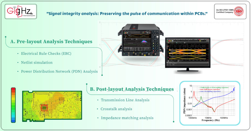
Before diving into the intricate design of a PCB, it is crucial to ensure that the signal integrity is preserved right from the beginning. This is where pre-layout analysis techniques come into play. Let’s take a closer look at some of these techniques.
- Pre-layout Analysis Techniques
Electrical Rule Checks (ERC):
During the initial stages of PCB design, we conduct Electrical Rule Checks (ERC) to make sure our designs comply with industry standards and best practices.
This helps us identify common design errors that could impact signal integrity, such as improper trace width, spacing, or clearance violations. By catching these issues early on, we can make the necessary adjustments and ensure the quality of our signals.
Netlist simulation:
Another technique we use is netlist simulation. With specialized tools, we analyze the behavior of the circuit and evaluate important signal characteristics like voltage levels, timing, and noise margins. Simulating the propagation of signals allows us to catch potential issues even before we move on to the PCB layout stage.
It’s like having a virtual prototype that helps us fine-tune our designs for optimal performance.
Power Distribution Network (PDN) Analysis:
Power Distribution Network (PDN) analysis is another critical step we take.
We carefully assess factors like voltage drops and noise to ensure stable power delivery to the sensitive components on our PCB. By optimizing the power supply network, we contribute to maintaining signal integrity throughout the system.
2.Post-layout Analysis Techniques
After the PCB layout is complete, post-layout analysis techniques are employed to verify and further enhance signal integrity. These techniques are essential for high-speed signals found in automotive ECUs.
Let’s delve into some of the primary techniques used,
Transmission Line Analysis:
One of these techniques is transmission line analysis. High-speed signals require special attention, so we analyze the trace lengths, widths, and termination techniques to ensure proper impedance matching and minimize signal reflections.
This helps prevent distortions that could lead to data corruption or communication failures, ensuring excellent signal integrity.
Crosstalk analysis
We also conduct crosstalk analysis to mitigate interference between adjacent traces on the PCB. Through advanced simulations and analysis, we identify potential coupling effects that could degrade signal integrity.
By adjusting trace spacing or using shielding techniques, we can reduce crosstalk and ensure clean and accurate signal transmission.
Impedance matching analysis
Impedance matching analysis is crucial for minimizing signal reflections.
We align the impedance of signal traces and components to optimize signal integrity and maximize the efficiency of signal transfer.
This technique involves carefully routing the traces, implementing termination techniques, and optimizing matching networks.
By employing these analysis techniques throughout the design process, we can confidently deliver PCBs with exceptional signal integrity.
Our meticulous approach ensures that our boards perform reliably and meet the stringent demands of high-speed signals in automotive ECUs.
Eye Diagram Technique for signal integrity analysis in pcb
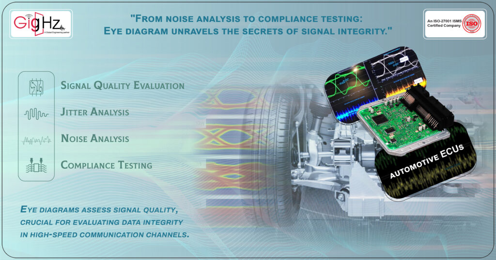
In addition to the signal integrity analysis techniques mentioned earlier, we also integrate the eye diagram technique into our signal integrity analysis process. The eye diagram provides valuable insights into the quality of signals and helps us evaluate data integrity in high-speed communication channels of layout or circuit.
With our expertise in constructing eye diagrams, we leverage the capabilities of an oscilloscope or specialized software like Mentor Graphics HyperLynx to sample the input signal multiple times and plot the results on a display.
This allows us to analyze and evaluate the signal integrity with precision.
This visual representation allows us to observe signal variations over time and assess signal quality.
The eye diagram technique serves several purposes in our PCB circuit design process:
Signal Quality Evaluation: By analyzing the eye diagram, we can assess various factors affecting signal quality, such as noise, timing errors, and amplitude variations. This helps us identify potential issues that could impact data integrity and take corrective measures.
Jitter Analysis: Jitter refers to the variation in timing between bits in a digital signal. By examining the eye opening in the diagram, we can quantify and analyze jitter, helping us optimize system performance and ensure reliable data transmission.
Noise Analysis: Noise can degrade signal quality and introduce errors. The eye diagram provides a visual representation of noise levels, allowing us to identify sources of noise and implement appropriate mitigation techniques.
Compliance Testing: The eye diagram is a common measurement used in compliance testing to ensure that a signal meets specific industry standards and requirements. By comparing the eye diagram against predefined mask limits, we can verify if the signal is within acceptable bounds.
By integrating the eye diagram technique into our analysis process, we gain deeper insights into signal behavior and can make informed decisions to optimize signal integrity.
It is an essential signal integrity analysis tool in ensuring reliable and robust communication in various industries, including automotive ECUs.
"Conduct the signal integrity analysis in PCB, your PCB design will never fail"
At GigHz, we understand the critical importance of signal integrity in PCB design.
That’s why we prioritize conducting thorough signal integrity analysis throughout the design process.
By doing so, we ensure that our PCB designs are robust, reliable, and able to meet the demanding requirements of modern electronic systems.
Preventing Signal Degradation:
- As we started with signal integrity analysis because, by conducting signal integrity analysis, we can identify and mitigate potential issues that could cause signal degradation.
- This helps in preserving signal integrity throughout the PCB design, leading to reliable data transmission and reducing the risk of errors or failures.
Value add here is ensuring clean and accurate quality of the signals, minimizing the chances of signal degradation and improving overall system performance.
Optimizing High-Speed Performance:
- Advanced analysis of signal integrity analysis allows for the optimization of high-speed performance by addressing timing errors, excessive jitter, and attenuation.
- By fine-tuning the layout, routing, and termination techniques, we can ensure efficient signal propagation, reduce signal distortions, and enhance the overall performance of high- signal speed communication.
The value add here is achieving superior high-speed performance, enabling the PCB to function reliably at higher speeds.
Meeting Industry Standards:
- Compliance with industry standards is crucial for the successful operation and integration of electronic systems.
- Signal integrity analysis ensures that the PCB design meets the required signal quality specifications set by industry standards.
This value add includes ensuring compatibility and interoperability with other components or systems, reducing potential issues during integration, and facilitating seamless operation within the larger system architecture.
Reducing Costly Iterations:
- Conducting signal integrity analysis during the design phase helps minimize the risk of signal integrity practices-related problems arising later in the development process.
- By proactively addressing signal integrity issues early on, costly iterations, rework, and delays can be significantly reduced.
This value add includes saving time and resources, streamlining the design process, and bringing the product to market faster.
Improving Design Efficiency:
- Signal integrity analysis provides valuable insights into signal behavior within the PCB.
- By understanding how signals interact with each other and their environment, we can optimize routing, stack-up, and component placement.
- This optimization improves design efficiency by reducing signal interference, optimizing signal paths, and minimizing the potential for noise or cross-talk.
The value add here is achieving an efficient design that maximizes signal integrity and minimizes unwanted signal interactions.
Enhancing Signal Quality and Reliability:
- The ultimate goal of signal integrity analysis is to ensure that signals remain clean, reliable, and accurately transmitted throughout the PCB.
- By addressing signal integrity issues early on, the overall quality and reliability of the PCB design are enhanced.
This value add includes ensuring data integrity, reducing the risk of errors or failures, and increasing customer satisfaction with a reliable and robust product.
Our Notable Upgrade: Engineering as a Service (EaaS)
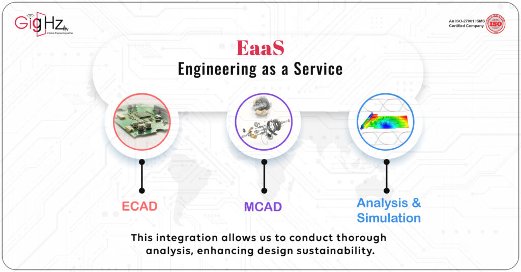
At GigHz, we take pride in offering comprehensive services that include ECAD, MCAD, analysis, and simulation.
These elements are vital parts of what we do, allowing us to provide exceptional value to our clients.
We harness the power of advanced technologies and simulation tools to enhance our design processes.
By following industry best practices and leveraging our extensive expertise, we ensure that our outcomes meet the highest standards of quality and performance.
Thorough analysis is at the core of our approach, enabling us to deliver designs that surpass expectations.
now, as the need for advanced and integrated engineering solutions keeps soaring, our Engineering as a Service (EaaS) are really stepping up the game.
We’re harnessing the power of ECAD, MCAD, and Analysis & Simulation. This gives us a great position to be frontrunners in this industry.
What’s really cool is that we offer a full package covering every single step of the engineering process.
And honestly, it’s this kind of approach that’s going to shape the future of our engineering.
It’s exciting stuff!
Why we do?
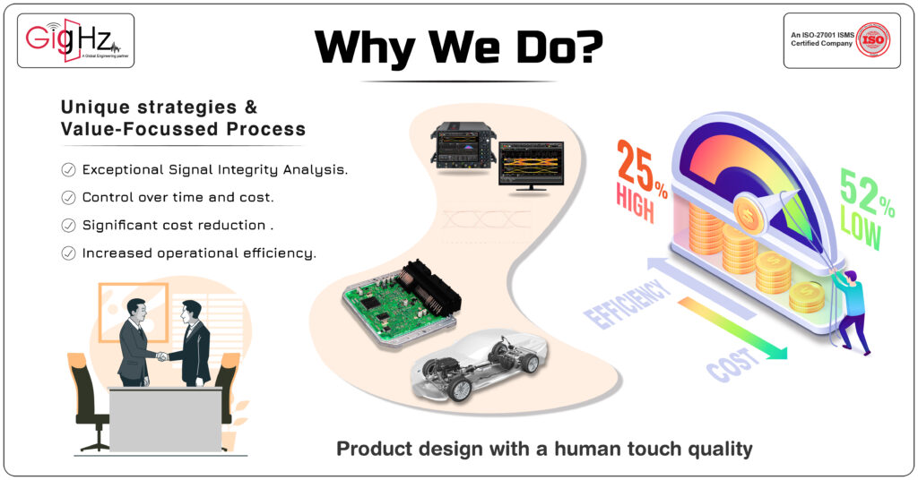
We embrace the challenge of providing exceptional Signal Integrity Analysis capabilities to the Automotive Industry. Our goal is to help you maintain control over both time and cost, all while elevating the quality of your product design with a human touch.
Despite the challenges in technology, we stand out from the competition due to our innovative methods and value-driven process.
This approach enables us to achieve a significant cost reduction of 52% while simultaneously increasing operational efficiency by 25%.
Conclusion
After conducting a research on signal integrity analysis in PCB design, we can conclude that signal integrity analysis is crucial in ensuring the success of PCB designs.
It helps identify and address potential issues such as reflection, crosstalk, delay, and impedance matching, which can lead to signal integrity issues.
Avoiding signal integrity issues in PCBs is a complex task that requires a deep understanding of design rules and techniques.
Designers must consider factors like losses, interference, and high-speed digital requirements.
Book a Demo call. Schedule a Free Consultation Now. https://calendly.com/gighz/30min
By adhering to signal integrity best practices and leveraging simulation tools, designers can mitigate potential signal integrity issues and improve the overall quality of their PCB designs.
“Ready to take your designs to the next level? Explore our in-depth services now.” https://gighz.net/services/