Have you ever finished a PCB layout, passed DRC checks, and felt confident — only to face unstable high-speed communication during testing?
Power stability seems fine.
Placement looks optimized.
Routing appears correct.
But when high-speed data transmission begins, unexpected signal instability can still appear.
Interfaces such as USB, Ethernet, and display links may start failing under load even when the schematic design is correct.
Often, the problem is not circuit logic or component selection.
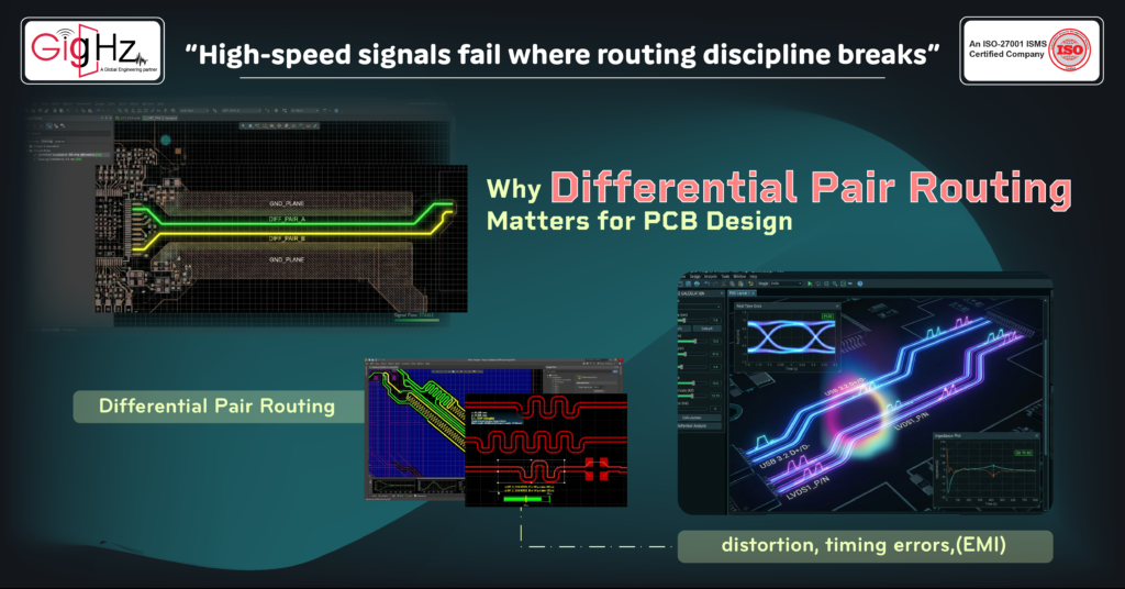
The real challenge is maintaining proper Differential Pair Routing discipline.
As signal frequencies and edge transition speeds increase, PCB traces behave more like transmission lines than simple copper connections. At this stage, routing must focus on signal integrity and electrical stability rather than only physical connectivity.
Proper routing protects high-speed signals from distortion, timing errors, and electromagnetic interference (EMI), ensuring reliable communication and product performance.
In modern high-speed electronic
systems, controlled routing is a fundamental design requirement.
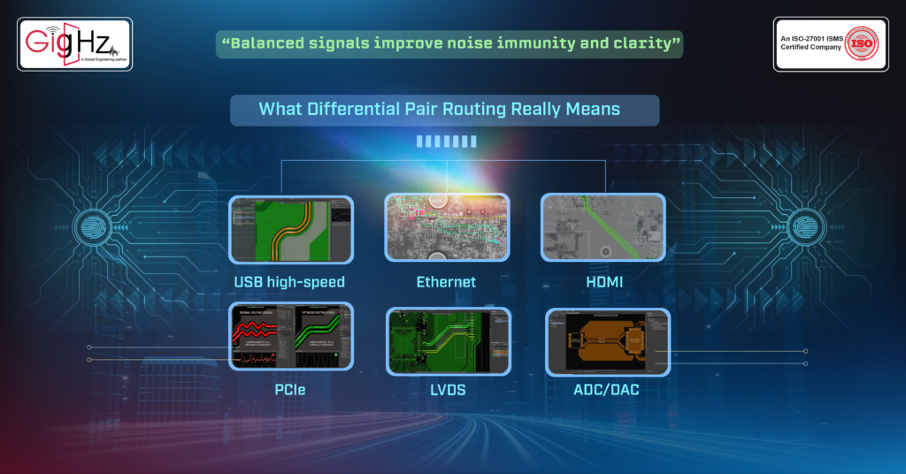
What Differential Pair Routing Really Means
Differential Pair Routing uses two traces to carry one signal.
One trace carries the positive signal.
The other carries the inverted version.
Instead of referencing signal voltage to ground, the receiver measures the voltage difference between the two traces.
External noise typically couples into both traces equally. Since the receiver measures the difference between them, common-mode noise cancels out. That cancellation improves noise immunity and signal clarity.
Because of this advantage, high-speed interfaces rely heavily on differential signaling, including:
- USB high-speed and SuperSpeed
• Ethernet (100 Mbps to multi-gigabit)
• HDMI and DisplayPort
• PCIe
• LVDS
• High-speed ADC/DAC interfaces
However, without properly controlled routing, these interfaces can become unstable even if the schematic is perfectly correct.
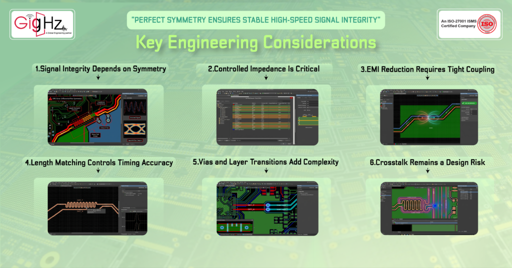
Key Engineering Considerations:
1. Signal Integrity Depends on Symmetry
Step 1: Initial Inspection & Documentation
High-speed signals are sensitive to impedance changes. Variations in trace width, spacing, dielectric environment, or vias can create reflections and distort waveform edges.
In Differential Pair Routing, both traces must behave electrically identical.
Symmetry can be disrupted by:
- Length mismatch
- Spacing variation
- Unequal vias
- Routing across plane splits
When balance is lost, signal quality drops — leading to jitter, eye diagram degradation, and reduced timing margin.
Differential routing is not just about parallel traces.
It’s about maintaining electrical balance across the entire path.
2. Controlled Impedance Is Critical
Differential impedance is determined by:
- Trace width
• Trace spacing
• Dielectric thickness
• Dielectric constant
• Copper thickness
• Distance to reference plane
If these parameters vary along the routing path, impedance changes. Impedance mismatch causes signal reflections.
At high data rates, even small impedance variation can create measurable signal degradation.
Stack-up planning must be finalized before routing begins. Adjusting trace geometry later to “make space” often leads to inconsistent impedance.
3. EMI Reduction Requires Tight Coupling
One of the biggest benefits of differential signaling is electromagnetic field cancellation.
When equal and opposite currents flow through tightly coupled traces, their magnetic fields cancel each other.
This reduces radiated emissions.
But that cancellation only works if the traces remain closely coupled throughout the entire routing path.
If spacing increases or loop area expands:
- Field cancellation weakens
- Radiation risk increases
- EMI compliance becomes harder
Proper routing minimizes loop area and maintains a continuous reference plane underneath the traces.
EMI control is not automatic.
It depends on routing discipline.
4. Length Matching Controls Timing Accuracy
Timing mismatch between paired traces is called skew.
Skew directly affects signal integrity at high speeds.
If one trace is longer than the other, the signals arrive at the receiver at slightly different times.
At gigabit speeds, even fractions of a millimetre can matter.
Excessive skew can result in:
- Reduced eye width
• Timing uncertainty
• Data sampling errors
• Increased retransmission rate
Length matching must follow the tolerance specified by the interface standard.
It should be verified using PCB design tool measurement features — not estimated visually.
Precision matters more as speed increases.
5. Vias and Layer Transitions Add Complexity
Layer changes introduce additional electrical variables. Each via adds parasitic inductance and capacitance.
If one trace transitions layers differently from the other, electrical imbalance occurs.
Return current continuity must also be maintained across reference planes.
If stitching vias are missing near transitions, the return path may become discontinuous.
This increases signal distortion and EMI risk.
Layer transitions in Differential Pair Routing must be:
- Symmetrical
- Electrically balanced
- Supported by continuous reference planes
Ignoring these details often causes issues that only appear during signal integrity testing.
6. Crosstalk Remains a Design Risk
Differential pairs are resistant to noise — but not immune.
If routed too close to high-energy signals such as:
- Switching regulators
• High-current power lines
• Fast clock traces
• Motor drivers
Electromagnetic coupling can still occur.
Dense layouts increase coupling probability.
Spacing guidelines should be defined before routing begins, not corrected at the end.
Differential routing works best when isolation planning is intentional.
Common Differential Pair Routing Mistakes
Many high-speed PCB issues come from small routing decisions.
Common mistakes include:
These may look minor during layout, but at high speeds, small inconsistencies quickly turn into signal instability.
Bottom Line
High-speed PCB problems rarely start with major design errors. They usually begin with small routing decisions that weren’t validated properly.
A slight skew mismatch.
A spacing variation.
An unnoticed impedance change.
At low speeds, those may not matter. At high speeds, they absolutely do.
Differential Pair Routing matters because it directly protects signal integrity, timing accuracy, and communication stability.
When routing is disciplined and verified early, performance becomes predictable — and redesign cycles become less likely.
In high-speed design, precision is not optional. It is the margin between stable operation and hidden failure.
Book a Call. Schedule a Free Consultation now. https://calendly.com/gighz/30min
Stuck in a loop of challenges? Always pick smart solution that works
Have you faced costly rework because 2D drawings skipped in MCAD workflows?
Effective way to prevent MCAD documentation errors recalls?
Please answer both poll questions before submitting.
Thank you for your response! 😊
Latest Post
Get Customized Engineering CAD Design Service

Book a Free Consultation Call
Partner with Gighz and bring your most innovative design concepts to life. Our engineering cad services accelerate development so you can focus on your big vision.