Here’s how to adapt MCAD 3d modeling from concept to creation
- Posted On:
- August 6, 2024
- Category:
- Mcad

3d Modeling
Welcome to our guide on adapting MCAD 3D modeling from concept to creation!
You’re in the right place if you’ve ever wondered how a product idea transforms from a sketch on paper into a fully functional, manufacturable product.
Today, we’ll walk you through the entire process using an automotive suspension system as an example to help you understand each step.
Imagine you want to create a suspension system that improves handling, provides a smoother ride, and is durable enough to withstand various road conditions.
But how do you take this idea and turn it into a tangible product that can be manufactured and used in vehicles?
This is where MCAD (Mechanical Computer-Aided Design) comes in.
MCAD is a powerful tool that allows engineers and designers to create detailed 3D models of their concepts. These models are not just digital representations; they serve as the blueprint for every part of the product. They specify how each component should be built, what materials to use, and how the parts will fit together to form a functional system.
Through MCAD, the journey from concept to creation becomes clear, efficient, and ready for production. Let’s take a deeper look at how this works!
Here's how to adapt MCAD 3d modeling from concept to creation

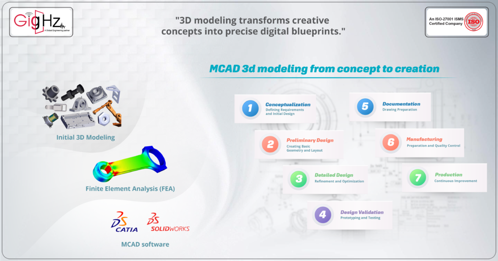
1.Conceptualization: Defining Requirements and Initial Design
Idea Generation and Sketching
Initiate the process by brainstorming various suspension system concepts aimed at enhancing vehicle handling and comfort.
Sketches and initial CAD concepts are developed to visualize different design approaches.
Requirements Analysis:
Specifications include load capacities, vehicle dynamics requirements (such as ride comfort and handling), durability expectations, and compliance with safety standards.
Functional requirements like wheel travel, camber control, and alignment parameters are crucially considered.
Feasibility Study:
Conduct feasibility studies to assess each concept’s technical, economic, and market feasibility.
Factors such as material availability, manufacturing capabilities, and cost implications are evaluated to select the most viable concept.
2. Preliminary Design: Creating Basic Geometry and Layout
Initial 3D Modeling:
Using MCAD software (e.g., CATIA, SolidWorks), create preliminary 3D models of the suspension system.
Basic geometries such as control arms, shock absorbers, springs, and mounting points are sketched out in digital space.
Concept Prototypes:
Digital prototypes are simulated to test basic functionality and performance aspects like kinematics and dynamic behavior.
This stage helps identify potential design flaws and assess initial feasibility before moving to more detailed modeling.
3. Detailed Design: Refinement and Optimization
Advanced 3D Modeling:
Detailed 3D models are developed to incorporate precise geometries, feature placements, and integration of subsystems.
Components undergo iterative refinement to optimize performance, weight, and manufacturability.
Material Selection:
Materials are chosen based on mechanical properties (such as tensile strength, fatigue resistance), weight considerations, and manufacturing requirements.
Advanced alloys for critical components, such as lightweight aluminum alloys for control arms and high-strength steels for springs, are typical choices.
Tolerance Analysis:
Tolerance stack-ups are analyzed to ensure proper fit and assembly of components under various manufacturing conditions.
GD&T (Geometric Dimensioning and Tolerancing) principles are applied to define dimensional tolerances critical for functional performance.
Simulation and Analysis:
Finite Element Analysis (FEA) is utilized to simulate structural integrity, stress distribution, and durability of components under realistic operating conditions.
Multibody Dynamics (MBD) simulations evaluate suspension kinematics, dynamics, and vehicle handling characteristics.
4. Design Validation: Prototyping and Testing
High-Fidelity Prototypes:
Prototypes are fabricated using rapid prototyping techniques (e.g., 3D printing, CNC machining) to validate the final design.
Prototypes replicate materials and manufacturing processes of production parts to assess performance accurately.
Testing and Validation:
Physical testing includes bench and vehicle-level tests to verify performance metrics such as ride comfort, handling agility, and structural durability.
Functional tests assess suspension travel, damping characteristics, and response to road inputs.
5.Documentation and Drawing Preparation
Engineering Drawings:
Detailed engineering drawings are created with precise dimensions, geometric tolerances, material specifications, and assembly instructions.
CAD models are annotated with notes and symbols to communicate critical information to manufacturing teams.
Bill of Materials (BOM):
A comprehensive BOM lists all components, subassemblies, raw materials, and quantities required for production.
Part numbers, descriptions, and sourcing information are included to facilitate procurement and assembly.
6.Manufacturing Preparation and Quality Control
Manufacturing Planning:
Detailed process plans outline manufacturing steps, tooling requirements, and quality control checkpoints.
Lean manufacturing principles are applied to optimize production efficiency while maintaining high-quality standards.
Supplier Collaboration:
Collaborative partnerships with suppliers ensure timely delivery of materials and components that meet design specifications.
Supplier quality audits and inspections are conducted to verify compliance with agreed-upon standards.
7. Production and Continuous Improvement
Full-Scale Production:
Production commences following pilot runs and validation of manufacturing processes.
Continuous monitoring and quality checks are implemented to detect and rectify production deviations.
Continuous Improvement:
Production and field performance feedback loops inform ongoing design refinements and process enhancements.
Data-driven analytics and customer feedback drive iterative improvements in future product iterations.
Why is it important to consider 3d modeling?
MCAD 3D modeling is crucial in PCB design for ensuring accurate component placement and clearance, preventing mechanical conflicts, and optimizing thermal management through heat dissipation simulations.
It also enhances structural integrity by analyzing stress and strain, integrates seamlessly integrates with ECAD for synchronized designs, and facilitates virtual prototyping to reduce costs.
Additionally, it ensures manufacturability through DFM and DFA analysis and improves communication with stakeholders by providing detailed technical documentation and 3D visualizations.
Our 3d Modeling Services

Our 3D Modeling Services Include
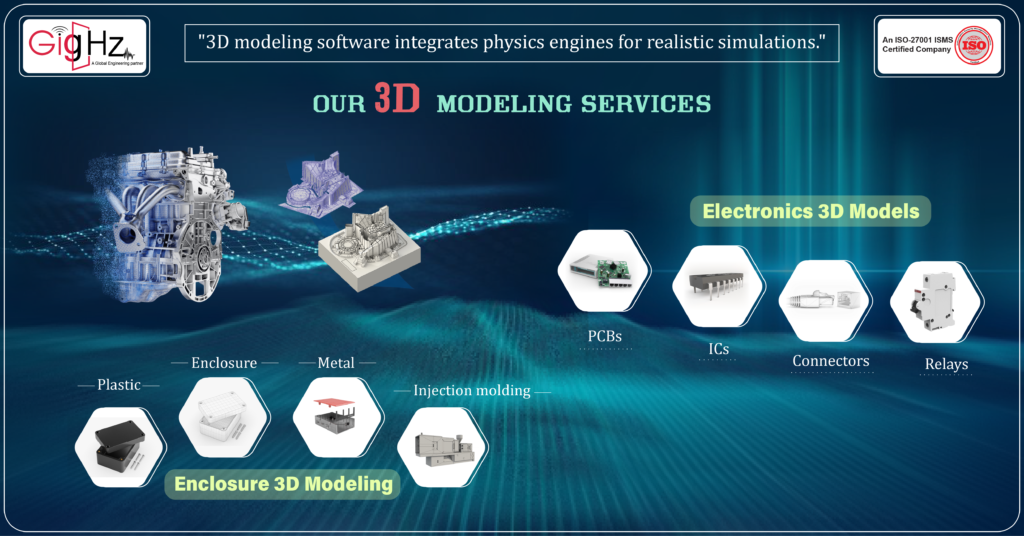
Electronic Component 3D Models
We utilize advanced CAD tools to create high-precision 3D models of various electronic components, ensuring accuracy for simulation, documentation, and manufacturing. Our skilled engineering team develops comprehensive component libraries tailored to your specific needs, using datasheets and specs to produce detailed models.
We create 3D models of:
- Printed Circuit Boards (PCBs)
- Integrated Circuits (ICs)
- Connectors, Cables, and Wires
- Switches, Relays, and Passive Components
- Housings, Cases, and Internal Structures
Enclosure 3D Modeling
We specialize in precise 3D modeling of enclosures and housings for electronics, machinery, and various other products. Using powerful CAD software like SolidWorks, we bring concepts to life, ensuring the models are ready for manufacturing.
We create 3D models of:
- Plastic and Metal Housing Designs
- Component Integration and Clearances
- Tooling Design for Injection Molding
- Structural Analysis with Finite Element Analysis (FEA)
- Photorealistic Rendering
- Drawings and Model Files for Prototypes
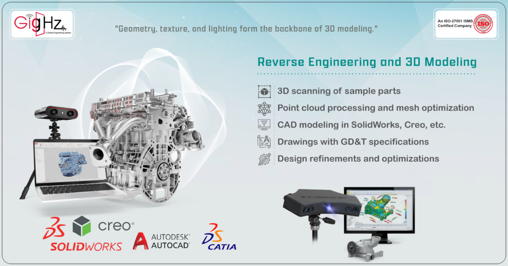
Reverse Engineering and 3D Modeling

We use reverse engineering to convert your physical components into fully detailed 3D CAD models. By capturing precise geometry data through in-house scanning, our engineers recreate parts, assemblies, and drawings from scratch with accuracy and efficiency.
Our reverse engineering process includes:
- 3D Scanning of Sample Parts – Capturing detailed data from physical components.
- Point Cloud Processing and Mesh Optimization – Converting scan data into usable 3D models.
- CAD Modeling in SolidWorks, Creo, etc. – Recreating parts and assemblies with precise CAD models.
- Drawings with GD&T Specifications – Providing detailed drawings with Geometric Dimensioning and Tolerancing (GD&T) for manufacturing.
- Design Refinements and Optimizations – Enhancing designs for performance, manufacturability, and cost-effectiveness.
Final Thoughts
In conclusion, it is clear that the platform offers a comprehensive solution for design data management within the library.
With the ability to import and export 3D MCAD models, users can easily exchange accurate 3D component models.
By the end of this guide, you’ll clearly understand how to take an idea and, using MCAD 3D modeling, turn it into a real, manufacturable product.
Stay updated on our services—connect with our founder on LinkedIn: https://www.linkedin.com/in/chandra-thimma/recent-activity/all/
Table of Contents
Latest Post
Get Customized Engineering CAD Design Service

Lorem ipsum dolor sit amet, consectetur adipiscing elit. Ut elit tellus, luctus nec ullamcorper mattis, pulvinar dapibus leo.
Book a Free Consultation Call
Partner with Gighz and bring your most innovative design concepts to life. Our engineering cad services accelerate development so you can focus on your big vision.
