Automotive ECU Enclosure Design
Imagine the ideal electronic product- You’ve achieved operational hardware design and perhaps even have the best firmware, yet you don’t have the right enclosure to accommodate it!
Water/moisture ingress can damage the product, while operational vibrations may dislodge cables and connectors. Additionally, the boxes are prone to breaking upon impact, and the overall appearance may lack a professional look and feel for users. The bottom line is that the product won’t last.
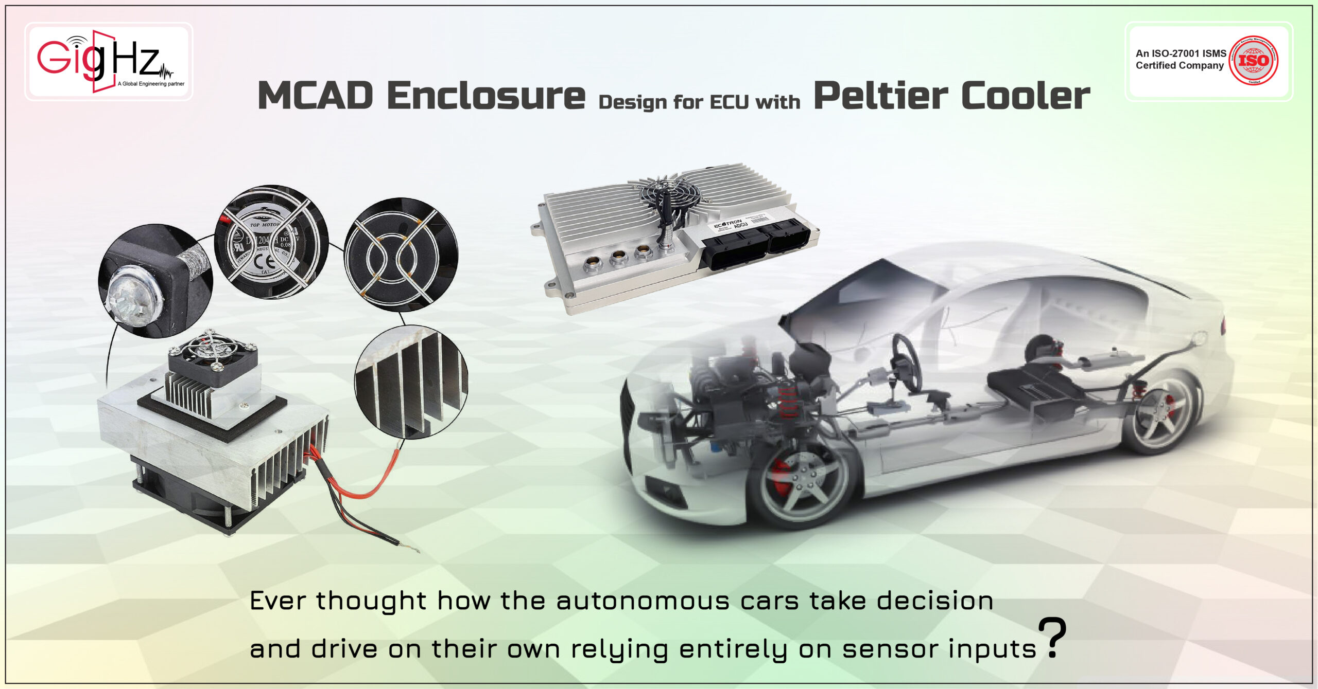
Autonomous vehicles are highly talked about these days, drawing a lot of attention due to their impressive performance and features. Ever thought about how autonomous cars make decisions and drive on their own relying entirely on sensor inputs? Not only do they do so, but they often outperform humans by making the right decisions at the right time.

Category :
Published Date :
December 5, 2023
Category :
Published Date :
December 5, 2023
Category :
Published Date :
December 5, 2023
Here comes the most crucial and responsible unit which is the Electronic Control Unit (ECU), which is behind all these core operations.
The Electronic Control Unit (ECU) domain controller is the core of ADAS, performing supervisory control of the vehicle based on information from surrounding equipment like stereo cameras, radar, and other sensors.
How can a single device take care of such plenty of information?
It’s indeed a highly challenging task.
Due to this overhead, there is a high chance of the device getting heated, requiring a proper cooling design for effective implementation.
We are taking you to a long way along the entire development process.
What is an ECU Enclosure Design?
The ECU enclosure design constitutes an automotive housing that contains a printed circuit board (PCB) along with input/output (I/O) connectors. An ECU, a compact device, manages various electrical systems within a vehicle. Initially representing an “engine control unit,” the ECU has evolved to encompass any electronic unit within a vehicle.
Importance of Enclosure Design for ECU in Automotive Sector
Enclosures in industries shield electrical and mechanical equipment from both external and internal conditions. Within the automotive sector, the design of enclosures for Electronic Control Units (ECUs) holds significance in minimizing EMI (Electromagnetic Interface) among systems, thereby preventing potential performance and reliability concerns.
Know more about EMI/EMC Analysis
A Journey of Innovation and Practical Solutions
Integrating Peltier Cooler into ECU Enclosure Design
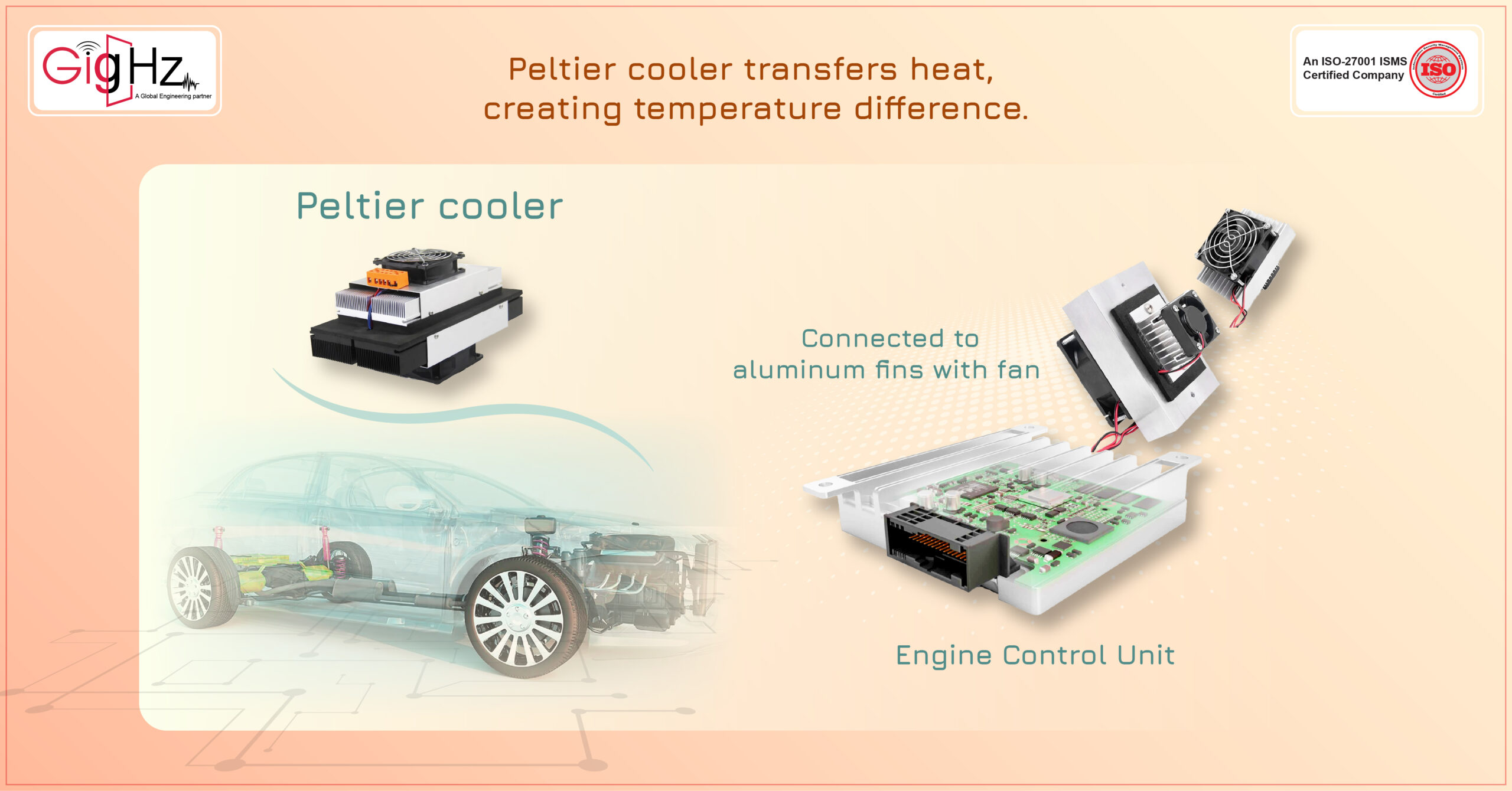
Our project design incorporated a Peltier cooler and an enclosure specially meant for ADAS applications. It is a great innovative idea from a client who contacted us for design implementation.
You may think what’s the special with a Peltier Cooler?
A Peltier cooler is a device that uses the Peltier effect to transfer heat from one side of the device to the other, creating a temperature difference. The Peltier effect is the phenomenon of electric current producing heat or cold at a junction of two different materials and vice versa.
When a direct current is applied to the device, one side becomes hot and the other side becomes cold. The hot side is connected to aluminum fins with a fan to cool it faster. The Cold side is connected to the processor of the ECU for better performance.
Challenges We Encountered In MCAD Enclosure Design For ECU
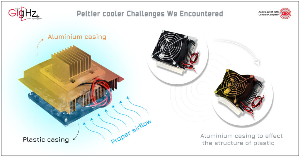
Challenges are a part of the Design process. The more challenges we face the more we expertise.
Notably, we needed to ensure proper airflow through the fins to effectively cool the Peltier cooler.
We tackled those issues through a comprehensive brainstorming session with our technical team to develop an effective work process.
Product Development Process
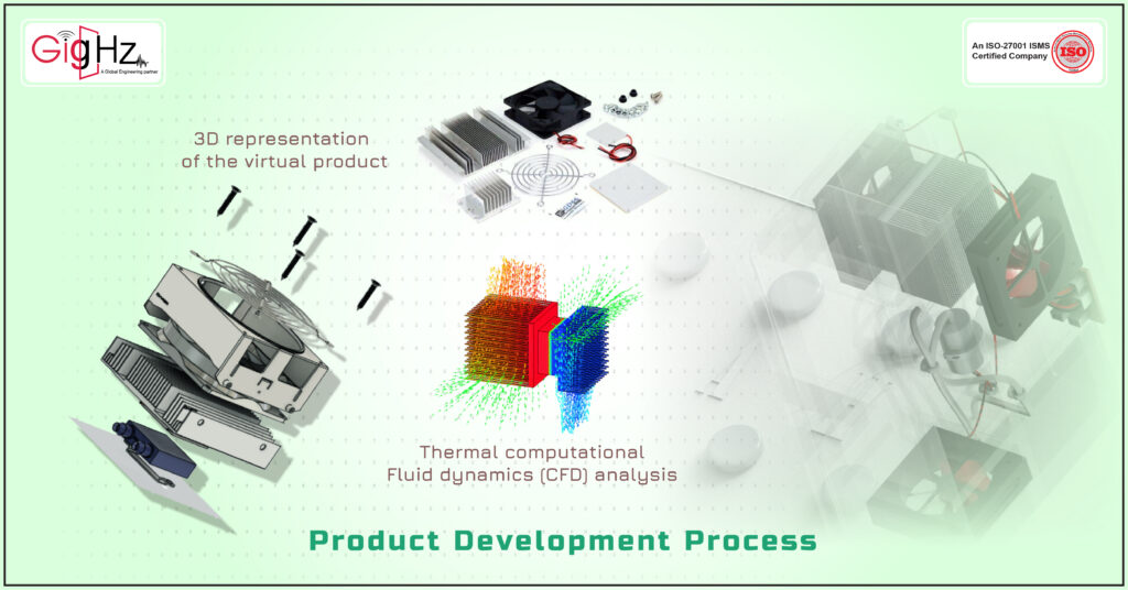
The brainstorming process worked well, and the workflow process was created as BOM Planning and material selection, Calculation for fins, Rough 3D planning, 3D development in tools using SolidWorks, Preparing Mesh & creating material properties for Analysis, Thermal CFD Analysis using Ansys, Design-Based modification on Analysis result, and 2D Engineering drawing development.
Also, Read more about GigHz’s Thermal Analysis Services
With continuation, as a part of the lifecycle we were involved in was 3D development of the actual design in SolidWorks. After the 3D model is developed, the preparation of the Mesh & creating material properties for the Analysis process is done. Preparing the mesh was a quick task, but when it came to material properties, it presented the highest challenge in finding all the required properties for the specific materials used in every part, from Peltier to enclosure.
Know more about GigHz’s 3d Modelling Services
Some material properties were created with basic values for properties that had no major impact on the results, which posed a challenge to complete.
With completion, the next step was to perform thermal computational fluid dynamics (CFD) analysis using Ansys. This was a crucial stage to simulate how heat was transferred within the product and how it interacted with the surrounding environment.
It helped us to understand the thermal performance and identify potential issues such as hotspots, along with finding inadequate heat dissipation areas.
Once the thermal CFD analysis was complete, the results were reviewed, and necessary design modifications were made to make the design robust. This involved changing dimensions, fin count, and area to improve the overall design’s thermal performance. It was an iterative process to fine-tune the design based on the analysis findings.
Lastly finalizing the 3D model with the client, the next step was to create detailed 2D engineering drawings. These drawings provided precise specifications, dimensions, tolerances, and other critical information needed for manufacturing.
They served as a bridge between design and production, ensuring that the product was manufactured accurately and efficiently.
Overall, the product development process involved a systematic approach from planning and material selection to detailed design, analysis, and final engineering drawings, ensuring the development proceeded on time.
Despite the challenges presented by the Peltier cooler, we distinguish ourselves through innovative methods and a value-driven process
This idea is changed to reality through our process and the accurate files that are required for manufacturing are delivered on time.
Engineering As A Service
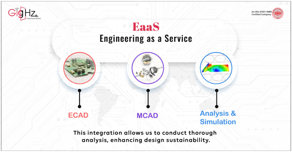
Our strong commitment to custom electronics enclosure design involves bringing together ECAD, MCAD, Analysis, and simulation to make design, production, and operations work more efficiently.
Engineering as a Service (EaaS) in a bundled platform combining ECAD (Electronic Computer-Aided Design), MCAD (Mechanical Computer-Aided Design), and Analysis and Simulation tools can streamline the product development process.
This integration allows us to conduct a thorough analysis, enhance design sustainability, and provide innovative solutions that result in cost savings and high-quality outcomes, all within an efficient timeline.
Why We Do?
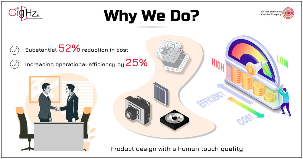
We take on the Peltier cooler challenge with MCAD enclosure design and 3D modeling to achieve a substantial 52% reduction in costs while simultaneously increasing operational efficiency by 25%, thereby transforming product design with a human touch of quality while also meeting harsh environmental requirements.
There is no greater satisfaction than achieving a customer’s trust and contentment, and we are delighted to have attained this through the persistent hard work and innovative designs of our technical team.
How to Achieve High Reliability in ECU Enclosure Design?
To ensure optimal performance and durability, high reliability in ECU enclosure design requires several critical considerations. Here are some key strategies for improving ECU enclosure design reliability:
Material Selection: Choose materials that are compatible, strong, long-lasting, and resistant to environmental elements like heat, moisture, chemicals, and vibration. Use materials that meet the required specifications, such as aluminum, stainless steel, or specialized plastics.
EMI Shielding: Create a reliable and effective electromagnetic interference (EMI) shielding technique in the ECU enclosure design to avoid interference that could impair ECU functionality. To reduce electromagnetic noise, use conductive gaskets, shielding coatings, or Faraday cage principles.
Sealing and Ingress Protection: Ensure that the ECU enclosure design incorporates effective sealing mechanisms such as gaskets, o-rings, or seals to keep water, dust, or other contaminants out of the ECU. Follow IP (Ingress Protection) standards appropriate for the intended application.
Thermal Management: Thermal management involves addressing heat dissipation within the enclosure through the use of proper ventilation, heat sinks, or thermal interface materials. Maintaining optimal operating temperatures prevents overheating and extends the life of components.
Mechanical Integrity: The ECU enclosure design should be designed to withstand mechanical stress, such as impacts, vibrations, and shock. To improve structural integrity and reduce the risk of damage during operation or transportation, use strong construction and mounting methods.
Environmental Considerations: Evaluate the operational environment and ensure that the ECU enclosure design takes into account specific conditions such as extreme temperatures, humidity, or chemical exposure.
Conclusion
It is seen that the meticulous planning, analysis, and design efforts led to a successful and timely project outcome.
We help our clients improve efficiency and reliability by providing accurate calibration results, which the high-quality 3D designs for mechanical enclosures were made with the aid of visual solutions. GigHz ECU enclosure design is tailored to fit your board, enabling a clear visualization of the actual product.
If you are in sync with our approach and progress, you are in the right place.
Are you curious about our approach? Book a Free Consultation with our Founder.
Reach us at https://calendly.com/gighz/30min
