How Power Integrity Failures Lead to Costly Redesigns in PCB Companies
- Posted On:
- December 9, 2025
- Category:
- Ecad
In any PCB company, the real pain usually starts after the first batch of boards comes out.
On the screen, everything looks perfect: traces are clean, components are positioned beautifully, and simulations are without any red flags.
But when the board is powered up, voltage ripples that appear, ICs behave unpredictably, and some circuits fail to start.
That’s when the engineers notice that the problem doesn’t lie in individual components or logic but rather in power distribution and stabilization through the layout.
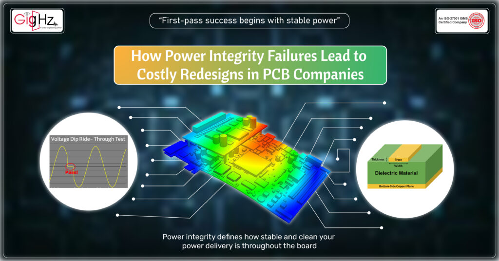
Power integrity defines how stable and clean your power delivery is throughout the board.
It decides whether your high-speed signals, processors, and analog sections get the right voltage at the right time.
Yet, it’s one of the most ignored aspects during design. And when it fails, it doesn’t just cause technical trouble — it leads to redesigns, production delays, and lost time that no PCB companies can afford.
Let’s understand how power integrity failures quietly turn into costly redesigns, and what can be done to prevent them.
What Power Integrity Really Means in PCB Design
Simply put, power integrity is the capability of your PCB’s power delivery network to deliver a stable voltage and current to all components under each operating condition.
It’s more than just connecting the power rail from the regulator to the ICs; it’s about how that power actually travels through copper planes, vias, and capacitors without creating unwanted noise or voltage drops.
You may notice voltage fluctuations, or ripple, or ground bounce, or random resets at high load conditions when power integrity is poor.
These issues are not visible at the time of schematic design but show up during functional testing or later in production.
For example, a microcontroller might reset when another chip switches suddenly, or an FPGA might not configure properly due to voltage drop.
In other words, power integrity is the silent foundation for every signal, clock, and logic transition.
Without it, even the most carefully routed signal integrity can fail.
Common Power Integrity Failures That Trigger Redesigns
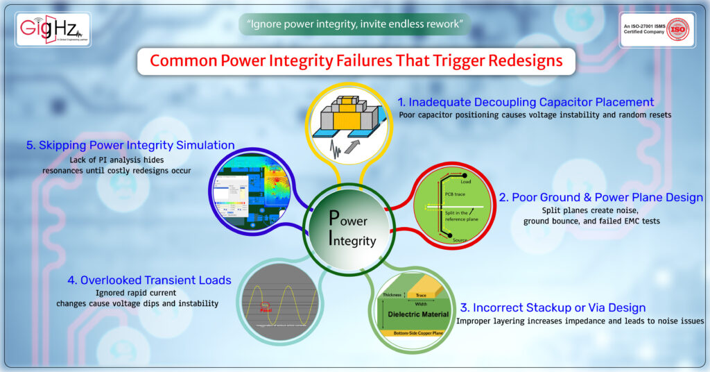
1. Inadequate Decoupling Capacitor Placement
Many designs fail because of poor capacitor placement. Designers often add decoupling capacitors as a formality, adding one near each IC and moving on.
But placement matters as much as quantity.
Such boards can sometimes exhibit random resets or clock instability during testing.
The engineers spend days trying to trace the cause, only to find out that it’s a simple power delivery problem that could have been avoided by placing the capacitors closer to the pins.
2. Poor Ground and Power Plane Design
A solid ground and power plane are the backbones of any stable design.
When planes are split or poorly connected, return currents find longer paths resulting in high impedance and noise coupling.
This sets up ground bounce, wherein the reference ground level itself fluctuates during operation.
The result? Sensitive analog circuits show unexpected noise, digital signals misbehave, and EMC tests fail.
Such boards are rejected in the validation stage at many PCB companies, forcing the layout team to rebuild the stackup and re-route the design entirely.
3. Incorrect Stackup or Via Design
Power integrity isn’t just about components; it’s about how the layers and vias distribute the current.
If the power and ground planes are separated by a thicker dielectric, the interplane capacitance decreases, increasing impedance and noise – because of thicker dielectric spacing that reduces interplane capacitance.
This increases impedance and makes the board more prone to noise.
Similarly, vias with long barrels or too few return vias can restrict current flow between layers.
This may not be visible in a schematic but becomes clear during load switching or high-speed testing.
Once these problems appear, there’s no quick fix — the board must be re-laid out.
4. Overlooked Transient Loads
Modern processors, FPGAs, and ASICs can change their current demand in microseconds.
When designers underestimate these transient loads, the power rails can overshoot or drop momentarily, causing unpredictable system behavior.
Many companies find this out during system integration when the board fails under real-world conditions.
The only solution then is to redesign the power delivery section, which can often involve regulator replacement or adding more capacitors.
Each change adds new prototypes, new validation cycles, and more cost.
5. Skipping Power Integrity Simulation
Skipping power integrity analysis is one of the biggest reasons for redesign.
While most ECAD tools now have native PI simulation, many teams avoid it due to time constraints.
They rely on experience or “known good” layouts — but every board is different.
It’s impossible to see resonant frequencies, impedance peaks or transient behavior under load without simulation.
By the time these are visible on the bench, the design is already fabricated, and redesign is inevitable.
The Real Cost of Power Integrity Failures
Every time a board fails due to power integrity, the financial impact of that goes far beyond reprinting PCBs.
Engineering Time: Teams spend days debugging what looks like a logic or component issue, only to discover later what the real cause is.
Layout engineers, signal specialists, and test teams get pulled into rework cycles that could’ve been avoided.
Manufacturing Cost: Every redesign opens the door to new prototypes, new stencils, new components, and new test hours.
Even minor changes such as the addition of capacitors can change the layout, necessitating new gerbers and validation.
Business Impact: Deadlines slip, customers lose trust, and delivery schedules collapse.
To PCB companies operating on razor-thin margins, each re-spin can wipe out the profit of several projects.
Not infrequently, one single overlooked PI issue can cause delays of several weeks and add thousands of dollars in rework.
And yet, the fix is often something as small as a better capacitor layout or a properly defined ground plane.
How to Prevent Power Integrity Failures Early
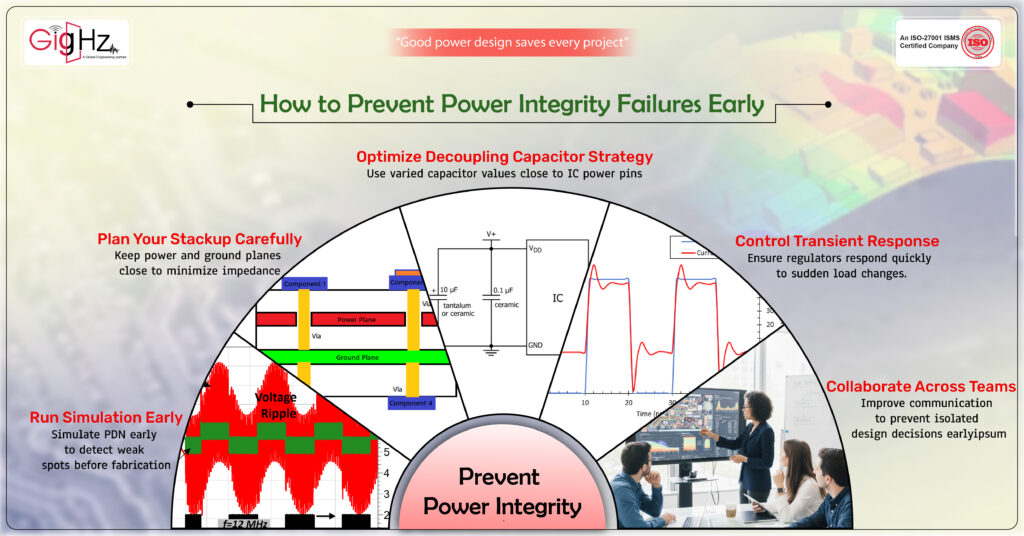
The best way to avoid redesigns is by making power integrity a part of your design culture and not a post-layout check. Here’s how:
- Run Power Integrity Simulation Early:
Use PDN analysis tools during layout and simulate impedance across frequency, ensuring it stays below target levels; this will reveal weak spots before going to fabrication.
- Plan Your Stackup Carefully:
Keep the power and ground planes as close as possible to minimize impedance and achieve better decoupling. Balanced stackup provides stable reference planes for all the layers.
- Optimize Decoupling Capacitor Strategy:
Use a mix of capacitor values (0.1 µF, 1 µF, 10 µF) and locate them physically close to each IC’s power pins. Keep trace lengths short and connections wide. - Control Transient Response:
Design the voltage regulators with adequate transient response bandwidth and phase margin to deal with fast changes in load. Verify transient performance using an oscilloscope during the testing of prototypes.
- Collaborate Across Teams:
Encourage communication between layout engineers, electrical designers, and mechanical teams.
Most power delivery problems result from design decisions made in isolation.
By integrating these steps early, you not only save money but also improve board reliability.
Every stable design instills confidence and reduces the risk of field failures.
Bottom Line
Power integrity is often treated as a secondary concern-something to check only if the board fails.
But in reality, it’s the difference between a successful first-pass design and a costly re-spin.
When you design with stable power delivery in mind, you don’t just avoid noise and ripple; you protect your reputation, your timelines, and your profit margins.
Every redesign avoided represents time saved, trust gained, and confidence built.
So, begin each project with a question: Is my power delivery network really stable? If the answer is yes, you’ve already prevented your next redesign.
Book a Call. Schedule a Free Consultation now https://calendly.com/gighz/30min
Stuck in a loop of challenges? Always pick smart solution that works
Have you faced costly rework because 2D drawings skipped in MCAD workflows?
Effective way to prevent MCAD documentation errors recalls?
Please answer both poll questions before submitting.
Thank you for your response! 😊
Latest Post
Get Customized Engineering CAD Design Service

Book a Free Consultation Call
Partner with Gighz and bring your most innovative design concepts to life. Our engineering cad services accelerate development so you can focus on your big vision.