It goes without saying that FMEA is supposed to prevent failure at any cost! But what if the failure starts where most people aren’t even looking?
Apparently, 4n schematic design are one of the most overlooked threats in modern electronics development. Now, teams focus on physical layout, simulations, and BOM validation, which is the earliest part of the PCB Design Process. On the other hand, ECAD schematic captures often get a free pass.
And that’s exactly where small oversights grow into big problems extensively!
Why This Matters?
Now, if your ECAD schematic capture is flawed in the first place, then, even the world’s best layout or components can’t save your design.
Likewise, we have seen critical errors from missing pull-ups on control lines to overlooked voltage mismatches and leads as well, for instance:
- Boards working properly in the lab, but failing in the field.
- Components getting damaged under normal operations.
- Costly reworking due to wrong reference voltages or ground loops.
Apparently, all of it because of the FMEA Checklist wasn’t applied during schematic design.
The 7 Checks Most Teams Miss During Schematic Verification
So,
here’s a very crucial list of FMEA Checklist items that should be baked into your ECAD schematic capture workflow!
Even before layout, simulation and obviously before it’s too late.
1. Check Signal Integrity Paths During Schematic Phase
Yes, before the layout comes annotating high-speed nets earlier is a must.
As a practice, flag differential pairs and ensure controlled impedance as captured.
You ask why?
Well, because signal routing intentions must originate from the schematic itself.
Additionally, identify nets that may require pre-layout signal integrity simulations—especially those needing IBIS model analysis.
Moreover, early identification allows in planning for simulations using tools like HyperLynx or Sigrity, ensuring signal integrity challenges are addressed proactively.
Also, high-speed net identification and planning must begin in the schematic to avoid issues later in the design flow.
2. Cross-Verify Power Domains & Decoupling Plans

At Gighz, over years we have seen how small inconsistencies in ECAD libraries can snowball into major setbacks — like delayed testing, integration failures, and even production reworks. Now, that’s why we strongly recommend embedding these rigor processes into your ECAD design processes.
So, here are our top recommendations for any team looking to bulletproof their ECAD workflow:
- Run a Full ECAD Library Audit Monthly: Don’t just check new components—revalidate legacy ones too. As, fresh eyes and automated tools can catch issues you missed.
- Automate Version Control: Whether you use Git, SVN, or a commercial solution, automate version control avoid file timestamps or manual folder names.
- Treat Symbols Like Code: Remember, every edit should go through peer review, rigorous testing, and clear documentation. Also, if you wouldn’t deploy code without review, don’t push a symbol or footprint either.
- Formalize Change Management: Set up a lightweight approval process for every library update. Prioritize change logs, clear justifications, and automate the impact analysis to prevent silent errors from spreading.
- Monitor and Train: Most importantly, make sure your team understands the reasoning behind all these processes. Also, offer quick refreshers or workshops to bring everyone up to speed on the tools and workflows.
- Formalize change management in ECAD: Finally, build a lightweight approval flow for every library update. Plus, make sure changes don’t just go live quietly.
Most importantly, the reality is that even one unnoticed change can derail an entire sprint. Just as we saw when a client lost nearly three weeks of testing effort to a subtle footprint error.
3. Review Grounding Strategy at a System Level
Then, use symbols and notes to define chassis vs. signal ground estimates beforehand. Also, annotate wherever isolation is needed and don’t leave it to layout guessing.
As most ground loops happen because of bad ECAD schematic capture assumptions.
4. Validate All Passive Defaults

Now, make sure that every 0-ohm resistor and DNP capacitor have a purpose! If not, then remove or flag them. Because, unused placeholders often get populated by severe mistakes.
Consequently, this one causes more field failures than you can think of.
5. Link Test Points and Measurement Plan
Evidently, include test points in your schematics. Then, define what’s measurable and where exactly. Most importantly, make them a part of the Schematic Verification process.
As a result, it saves debug time and increases test coverage extensively.
6. Label Every Critical Control Line Explicitly
Next, reset and enable, interrupt lines by labelling them clearly! Then, add direction arrows and logic level expectations wherever it’s necessary.
Therefore, it prevents boot failures, brownouts, and signal clashes.
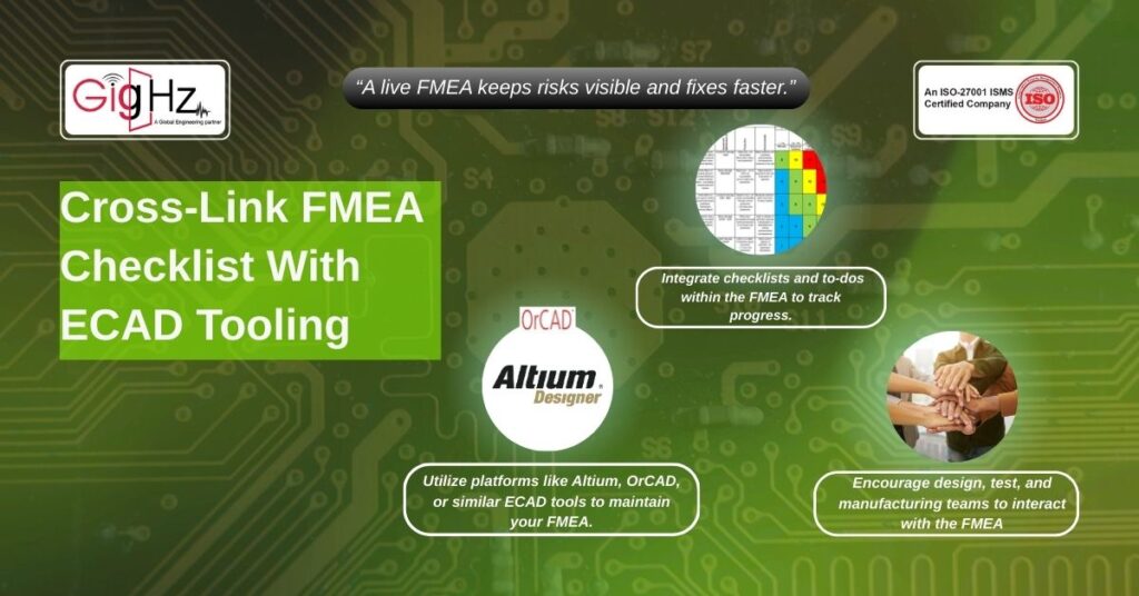
7. Cross-Link FMEA Checklist With ECAD Tooling

Finally, your FMEA should be a live document and not a PDF. Likewise, use tools like Altium, OrCAD, and etc to allow annotations and linked checklists.
Additionally, it ensures that tighter feedback loop = lower risk in the PCB Design Process.
What’s Really at Risk?
Summing up, skipping any of these isn’t just a checkbox error! Rather it’s a systemic design flaw in your entire process.
So, if your team isn’t applying the FMEA Checklist right inside the ECAD schematic capture phase – Clearly, you are just building on majorly guesswork.
Whereas, our clients who follow our schematic-level FMEA review reduce field failures by up to 30% and speed up validation by 2–3 weeks.
Tired of debugging avoidable schematic flaws?
We help teams embed FMEA right into their ECAD capture flow.
Likewise, by embedding FMEA directly into schematic capture, you’re not just reviewing after the fact—you’re engineering resilience from the very first line.
Plus, think of it as a proactive defense layer: every missed connection, misaligned constraint, or overlooked redundancy gets flagged before it ever becomes a downstream headache.
Also, the impact is tangible. Validation teams spend less time firefighting and more time refining. Manufacturing sees fewer design iterations, reducing both costs and lead times.
And most importantly, product reliability isn’t left to chance—it’s built in as a guarantee.
What sets our approach apart is that we don’t impose another tool or extra burden on your engineers.
Instead, our framework integrates seamlessly into their existing ECAD workflows, giving them actionable checkpoints, not added complexity.
The result?
Designs that are cleaner, audits that are faster, and launches that are smoother.
If you want to move beyond reactive fixes, FMEA-led schematic capture is the shift your process needs.
Stuck in a loop of challenges? Always pick smart solution that works
What’s the biggest schematic pain point causing costly re-spins?
What’s your go-to fix for schematic design errors?
Please answer both poll questions before submitting.
Thank you for your response! 😊
Latest Post
Get Customized Engineering CAD Design Service

Book a Free Consultation Call
Partner with Gighz and bring your most innovative design concepts to life. Our engineering cad services accelerate development so you can focus on your big vision.
