PCB Thermal Simulation Strategies to Keep Your Designs Cool
- Posted On:
- May 6, 2026
- Category:
- Analysis & Simulation
Have you noticed how modern electronic devices are becoming smaller but more powerful?
While this improves performance, it also creates a new challenge — heat management inside compact designs.
When components are packed closely, heat buildup can cause unstable operation, signal interference, and reduced product lifespan.
Fixing thermal issues after prototype testing can be expensive.
This is where PCB thermal simulation helps.
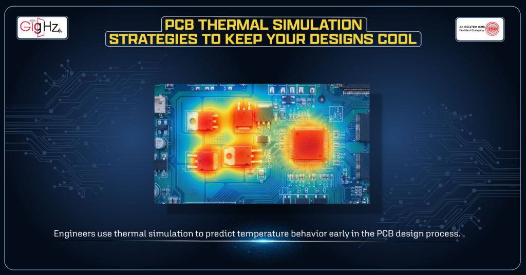
Instead of waiting for overheating problems to appear in physical prototypes, engineers use thermal simulation to predict temperature behavior early in the PCB design process.
Today, thermal challenges are not limited to high-power systems. Consumer electronics, embedded circuits, and high-speed designs also face heating issues because switching speeds are increasing and layouts are becoming tighter.
Understanding thermal control is the first step.
Now let’s explore practical strategies to improve PCB thermal performance.
Core PCB Thermal Simulation Strategies
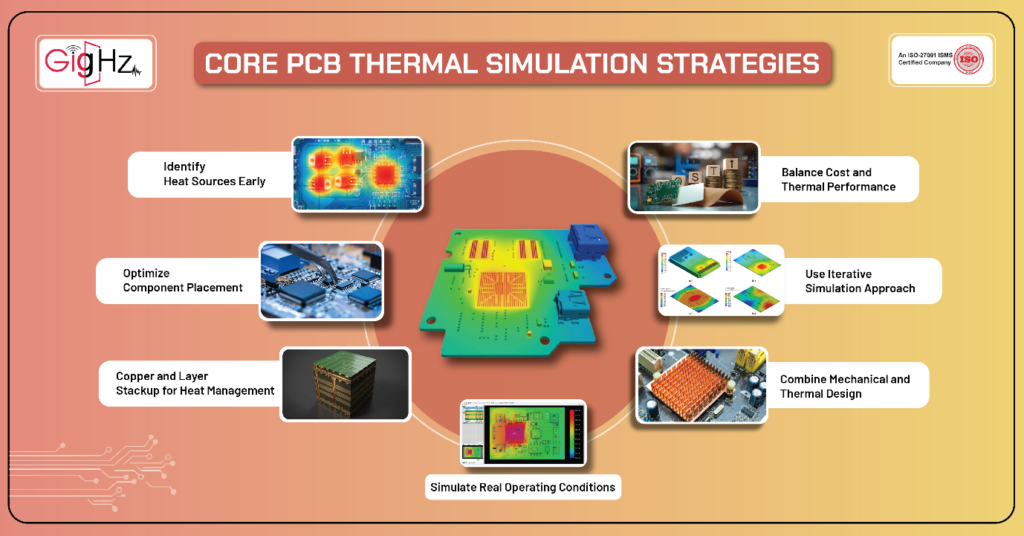
Strategy 1: Identify Heat Sources Early
The first step in thermal design is understanding where heat is coming from.
Common heat-generating components include:
- Voltage regulators
- High-speed processors and FPGA chips
- High-current connectors
- LEDs
- Motor drivers
- Power amplifier ICs
During schematic design, estimate power dissipation using datasheet data and expected loads to plan thermal behavior early and avoid hotspot issues.
This also helps prevent routing congestion and design changes later.
Strategy 2: Optimize Component Placement
Component placement strongly influences thermal optimization.
Try to follow these simple rules:
- Avoid placing multiple high-power components close together and separate heat-generating components from temperature-sensitive circuits.
- Also, align components with expected airflow direction inside the enclosure and leave enough spacing for natural heat dissipation.
Thermal simulation heat maps help optimize component placement early, reduce hotspots, and improve overall heat distribution and PCB thermal performance.
Strategy 3: Use Copper and Layer Stackup for Heat Management
Copper plays an important role in thermal management and electrical conductivity.
Improve copper usage by:
- Improve thermal performance by creating large copper pours connected to thermal pads, using solid ground planes for heat spreading, and adding thermal vias under power components.
- Designing multilayer stackup that allow smooth heat flow is also helpful.
Uneven copper distribution can create thermal stress, so simulation validation is important.
Strategy 4: Simulate Real Operating Conditions
One of the most common mistakes in PCB thermal simulation is using unrealistic assumptions.
Good thermal models should include:
- Ambient temperature ranges
- Enclosure airflow restrictions
- Component power profiles
- Natural and forced convection
For example, a PCB operating inside a sealed enclosure behaves very differently from one exposed to open air.
Using realistic conditions helps simulation results match real product performance.
Strategy 5: Combine Mechanical and Thermal Design
Thermal management is not only an electrical design problem. Mechanical structure also plays an important role.
You should consider:
- Heat sink mounting location
- Airflow channel design
- Ventilation opening placement
- Enclosure material and thermal insulation effect
- Clearance space around high-temperature components
Modern development workflows often combine ECAD and MCAD models to study airflow and heat movement inside the full product assembly.
Strategy 6: Use Iterative Simulation Approach
Thermal simulation works best when applied in multiple cycles rather than as a one-time check.
The design process usually follows these steps:
- Run the initial simulation to evaluate temperature distribution.
- Identify hotspot regions and thermal bottlenecks.
- Adjust component placement, copper area, or cooling method.
- Run the simulation again to confirm performance improvement.
Repeating simulation cycles helps maintain thermal safety margins while keeping design complexity under control and improving overall reliability.
Strategy 7: Balance Cost and Thermal Performance
Thermal optimization must balance performance, reliability, and manufacturing cost.
Consider these trade-offs:
- Increasing copper thickness may improve cooling but increases manufacturing cost.
- Adding cooling fans improves heat removal but may create noise and reduce reliability.
- Heat sinks help thermal performance but require space.
- High-performance components may cost more.
Simulation helps engineers choose the best balance between reliability and budget.
Common PCB Thermal Simulation Mistakes
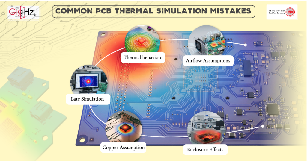
Avoid these common errors:
- Using unrealistic airflow assumptions.
- Ignoring transient thermal behavior.
- Running simulation too late in the design cycle.
- Assuming copper alone solves thermal problems.
- Failing to consider enclosure effects.
Avoiding these mistakes improves accuracy and prevents unexpected failures during testing.
Practical PCB Thermal Simulation Tips
Keep it simple and practical:
- Run thermal simulation before finalizing your PCB layout.
- Always test worst-case power and ambient temperature conditions.
- Leave enough spacing between high-power components.
- Use thermal vias and copper planes to spread heat effectively.
- Review airflow paths inside the enclosure design.
- Recheck thermal results after any major layout change.
- Keep thermal margins safe instead of designing too close to limits.
Final Thoughts
PCB thermal simulation has become a critical part of modern electronic design workflows. By identifying heat sources early, optimizing layout decisions, leveraging copper effectively, and modeling real operating conditions, engineers can prevent overheating before it becomes a problem.
The key is to treat PCB thermal analysis as a continuous process rather than a final check. When integrated throughout the workflow, thermal simulations reduce redesign cycles, improve reliability, and ensure your design performs as intended in real-world conditions.
In short, keeping your PCB cool is not just about adding cooling hardware — it is about making smarter design decisions from the very beginning.
Book a Call. Schedule a Free Consultation now. https://calendly.com/gighz/30min
Stuck in a loop of challenges? Always pick smart solution that works
Have you faced costly rework because 2D drawings skipped in MCAD workflows?
Effective way to prevent MCAD documentation errors recalls?
Please answer both poll questions before submitting.
Thank you for your response! 😊
Latest Post
Get Customized Engineering CAD Design Service

Book a Free Consultation Call
Partner with Gighz and bring your most innovative design concepts to life. Our engineering cad services accelerate development so you can focus on your big vision.