Fixing PCB Instability in Automotive Systems: Lessons from EV Failure
- Posted On:
- September 11, 2025
- Category:
- Ecad
So, whenever engineers think of failure in automotive electronics, they ponder upon weak components or bad solder joints.
But do you know what’s the real issue?
Well,
its PCB instability in automotive systems caused not by lack, but by over-design.
Now, we recently worked with a premium EV manufacturer that came to us after experiencing random resets and control failures in their main powertrain board.
Whereas, their in-house team had thrown every feature imaginable into the design redundancies, sensors and diagnostics.
However, the board just kept failing under the massive amount of load.
Now, the root cause wasn’t obvious at all!
But after a deep automotive PCB failure analysis, the cause surfaced up.
Apparently, the design had collapsed under its own set of complexities.
So, let’s break down how we solved it and what are the key takeaways.
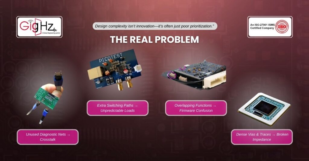
The Real Problem
Nowadays, modern automotive boards juggle a lot between CAN, LIN, Ethernet, multiple power rails, high-speed data lines, thermal constraints and the list will just keep going on.
On the other hand, it’s quite tempting to be “future-proof” by adding more features and flexibility.
But here’s what we often find during automotive PCB failure analysis:
- Unused diagnostic nets introduce crosstalks.
- Extra switching paths create unpredictable load paths.
- Overlapping functions confuse the firmware and power sequencing.
- Higher via and trace density disrupts impedance control
Also, these aren’t rare anomalies! Rather, they are the textbook definition of PCB design complexity pitfalls. Most importantly, they are more common than most engineers admit.
What Went Wrong: Feature Overload, Signal Breakdown

Evidently, even in majorly experienced design teams, it’s common to miss the subtle complexities at times.
So, here’s what we spotted in our analysis:
1. No EMI Ground Planes Near High-Speed Traces
In this case, the OEM almost had:
- Packed 14 separate sensor inputs for torque, voltage and thermal feedback.
- Then we used 6 different DC-DC conversion paths (2 of which were never used in production).
- Left debugging headers exposed in the final design.
During our automotive PCB failure analysis, we found EMI noise leaking through those unused headers. Additionally, one backup power path occasionally activated out of sequence causing voltage bounce that crashed the controller.
The Fix
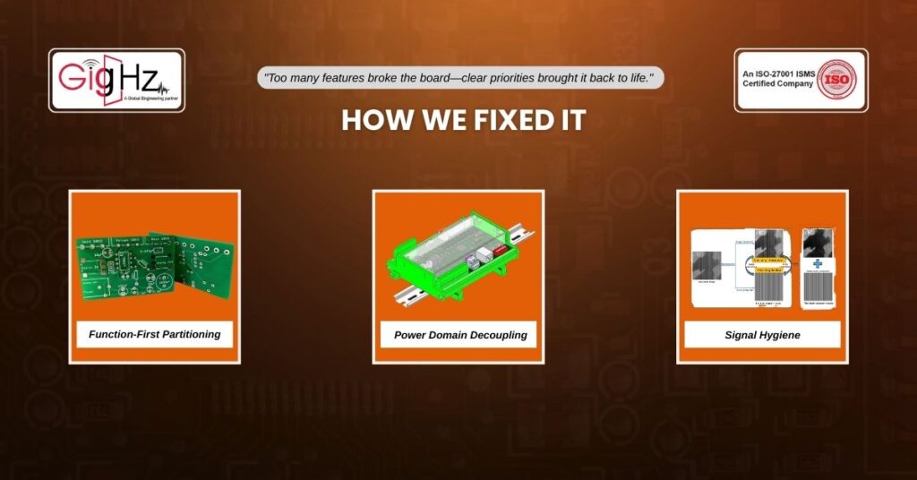
Accordingly, we rebuilt the entire board around these three principles:
- Function-First Partitioning: Firstly, we mapped out only what was essential for production, and removed every redundant trace and connector that wasn’t even validated.
- Power Domain Decoupling: Now, instead of multiple power paths crossing domains, we redesigned for strict sequencing and proper isolation. As a result, we had clean rails = stable logic.
- Signal Hygiene: Also, we re-routed critical signals to avoid any overlapping over noisy traces and buried unused nets deep in ground-poured layers.
Now, after two weeks of redesign and one prototype spin, the entire board passed all validation tests. Consequently, it resulted in no crashes and no unexplained resets. Apparently, it’s a classic case of pcb design complexity pitfalls leading directly to pcb instability in automotive applications.
What You Can Learn: Simpler = Safer

Evidently, most engineers think that failures come from what they forgot.
But in real-time automotive PCB failure analysis, the risk often lies in what you added unnecessarily.
In addition, PCB design complexity pitfalls might not show up in the initial CAD analysis. Then, they end up showing during EMC testing, thermal ramp-ups, or after 60 hours of running.
Therefore, if you design your board to do everything, it may end up doing nothing reliably.
A focused, purpose-driven design philosophy is critical—especially in safety-sensitive domains like automotive systems.
Engineers must embrace restraint and intentionality: every component, every trace, every added feature must justify its existence.
Overloading a PCB doesn’t just introduce complexity; it also increases the risk of thermal issues, electrical noise, and unexpected failure modes.
Here’s where over engineering typically hurts the most:
- Signal integrity degradation due to unnecessary sensors or communication lines.
- Thermal buildup from crowded layouts and redundant power paths.
- Increased EMC vulnerability from overlapping or poorly isolated functions.
- Troubleshooting complexity, making root-cause analysis harder in real-world conditions.
Instead of building a one-size-fits-all board, modular designs and function-specific optimization tend to be more sustainable.
Extra complexity can also create inconsistencies during manufacturing, such as variation in solder quality or inspection accuracy.
In most cases, the most reliable boards are those that do exactly what’s needed—no more, no less.
Avoiding overdesign improves testability, serviceability, and long-term robustness.
In the end, true reliability in automotive electronics isn’t about maximizing features—it’s about optimizing purpose and execution.
Bottom Line
Summing up, our teardown of this EV board revealed what many ignore which is pcb design complexity pitfalls that ruins your entire product.
So, by applying a focused redesign, we helped this client avoid months of debug and $100K+ in launch delays.
Likewise, this outcome highlights the real value of proactive design reviews and failure analysis.
Catching these issues before production ramps up not only saves time and money but also protects brand reputation and customer trust—critical factors in the competitive EV market.
In this case, our intervention turned a potential disaster into a successful product launch.
Hence, it’s a reminder that attention to detail at the design stage pays dividends down the road.
As systems grow more complex, the discipline of simplifying becomes even more important.
Stuck in a loop of challenges? Always pick smart solution that works
What’s the biggest cause of PCB instability in automotive systems?
What will be your solution to ensure reliability in automotive PCB designs?
Please answer both poll questions before submitting.
Thank you for your response! 😊
Latest Post
Get Customized Engineering CAD Design Service

Book a Free Consultation Call
Partner with Gighz and bring your most innovative design concepts to life. Our engineering cad services accelerate development so you can focus on your big vision.