How to Migrate ECAD Designs Without Losing Nets (Altium to Cadence)
- Posted On:
- September 11, 2025
- Category:
- Ecad
Clearly, switching ECAD tools shouldn’t feel like a massive challenge.
But too often, it does.
Apparently, for engineers migrating from Altium to Cadence poses a daunting task because one minute error in the conversion process can lead to severe critical consequences!
For instance, several lost nets, corruption in design data, then hours of reworking, and even worse like failed builds.
So, we recently helped a client shift their complete design ecosystem using our unique ECAD EDA conversion process.
Not only did we preserve every net, but we also improved their tool interoperability for smoother cross-team workflows.
Moreover, our team remarkably conducted it in under 72 hours only.
Therefore, let’s break down how we made it & how you can do it as well.
Why ECAD Conversions Are So Risky (and Necessary)
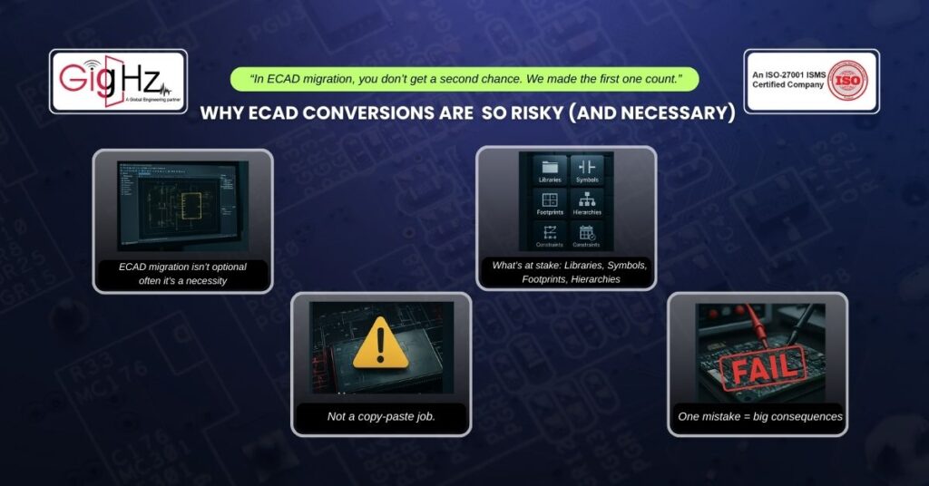
So, changing your ECAD platform is usually not a choice but rather a crucial necessity! Maybe your organization is standardizing tools or your new partner team works only in Cadence. Also, maybe you’re just tired of siloed workflows and limited collaboration.
But here’s the caution mark that most people just ignore:
- It goes without saying that ECAD conversion isn’t a copy-paste job. In turn, it’s a high-stakes data migration process involving libraries, symbols, footprints, hierarchies, and constraints.
Once, you have done it wrong, and you’re not just risking a bug! Instead you caused a major product delay.
Our Client’s Challenge
Now, the client has spent over 6 months developing an advanced board in Altium. However, with an ongoing merger underway, the entire design ecosystem had to shift for Cadence Allegro.
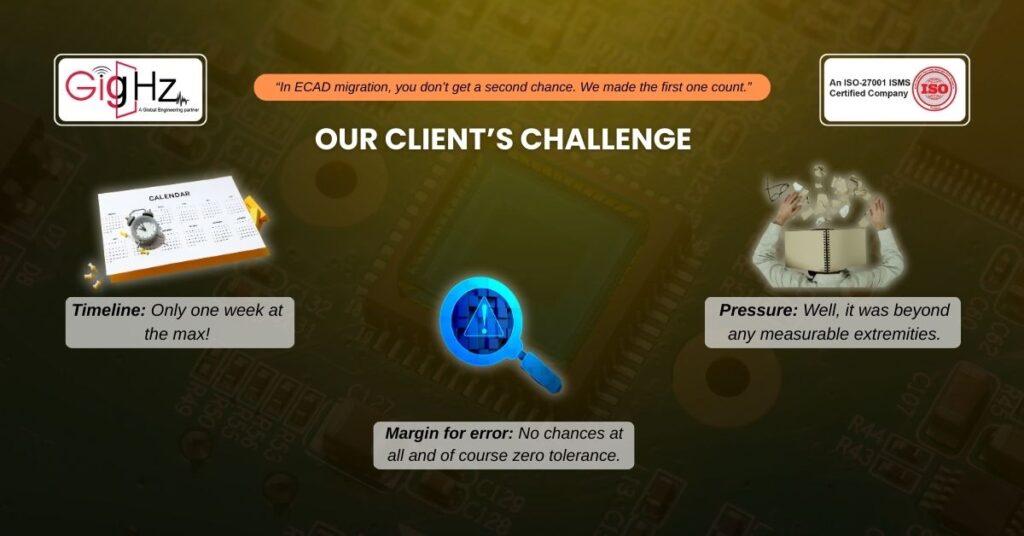
Additionally, the circumstances were:
- Timeline: Only one week at the max!
- Margin for error: No chances at all and of course zero tolerance.
- Pressure: Well, it was beyond any measurable extremities.
However, they approached us because they had done their worst-case research from their peers on ECAD conversion projects that took several months to complete! That too resulted in half-working files, broken libraries, and obviously lost nets.
Our ECAD-to-ECAD Conversion Framework
Evidently, we have handled dozens of conversions across tools like Altium, Cadence, Mentor, and Eagle. Likewise, our framework follows a very lossless, integrity-first approach that prioritizes:
- Design data integrity
- Tool interoperability
- Workflow compatibility
- Scalability for future designs
Speaking of which, let’s walk you through our exact conversion process.
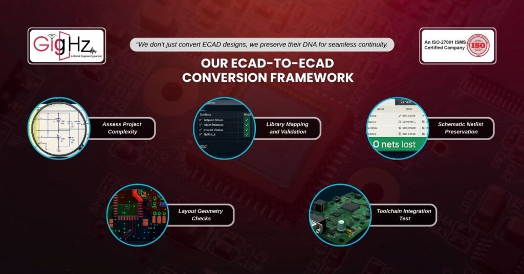
Step 1: Assess Project Complexity
So, before anything else, we run a comprehensive design data audit. Likewise it includes:
- Schematic hierarchy depth: To understand design complexity and signal flow across sheets.
- Special stackups or impedance constraints: To identify critical layers or high-speed requirements early.
- Custom symbols and footprints: To flag any non-standard components that may need manual handling.
- Hidden nets, buried vias, or embedded passives: To catch elements that could be lost or misinterpreted during conversion.
Also, this audit tells us about how complex the conversion will be and where potential pitfalls may occur
Step 2: Library Mapping and Validation
Now, here’s where most ECAD conversion attempts fail! Clearly, every ECAD tool has its own library logic and behavior. But, our approach leverages automated library translation tools, followed by manual footprint validation.
In accordance, we check for:
- Pin-to-pad alignment
- Layer stack compatibility
- Variant support
- ECAD-to-MCAD interoperability
Evidently, if you don’t catch issues here, you may expect tool interoperability issues later on.
Step 3: Schematic Netlist Preservation
Indeed, this is the prime part of the entire conversion process.
Likewise, we use custom scripting and sanity-check mechanisms to ensure every net in Altium maps correctly to the Cadence design. Afterwards, we do a diff-check between original and converted netlists.
As a result, we have zero net loss, clean and consistent workflow.
Step 4: Layout Geometry Checks
Now, most teams assume that if the schematic looks fine then the layout will too. But, it’s not true at all.
Hence, we always consider running the following checks:
- Clearance checks
- Plane merge validation
- Via definitions and design rules
- Constraint region mapping
Especially in Altium to Cadence conversions, copper behavior and spacing rules don’t always carry over. Therefore, you must catch it here, or face costly design data integrity issues later.
Step 5: Toolchain Integration Test
Finally, once the design is in cadence, we simulate the entire toolchain:
- DRC
- ERC
- 3D MCAD export
- Manufacturing output
- Gerber preview
Why, you ask? Well, because tool interoperability doesn’t end at the schematic only as it also affects manufacturing, testing, and beyond.
Bottom Line
Summing up, our teardown of this EV board revealed what many ignore which is pcb design complexity pitfalls that ruins your entire product.
So, by applying a focused redesign, we helped this client avoid months of debug and $100K+ in launch delays.
Likewise, this outcome highlights the real value of proactive design reviews and failure analysis.
Catching these issues before production ramps up not only saves time and money but also protects brand reputation and customer trust—critical factors in the competitive EV market.
In this case, our intervention turned a potential disaster into a successful product launch.
Hence, it’s a reminder that attention to detail at the design stage pays dividends down the road.
As systems grow more complex, the discipline of simplifying becomes even more important.
Stuck in a loop of challenges? Always pick smart solution that works
What frustrates you the most when migrating ECAD designs?
What’s the #1 outcome you’d expect from an ECAD migration?
Please answer both poll questions before submitting.
Thank you for your response! 😊
Latest Post
Get Customized Engineering CAD Design Service

Book a Free Consultation Call
Partner with Gighz and bring your most innovative design concepts to life. Our engineering cad services accelerate development so you can focus on your big vision.