Mcad

7 Step by Step Guide to select right components for MCAD Enclosure Design

MCAD Enclosure Design Hey there! Smileful day to all! Being aware of new innovations is highly beneficial for enhancing our experience and expanding our knowledge, don’t you think? During a web search in the medical industry, a report on eyesight, highlighted challenges faced by the medical field, in designing MCAD enclosures. The report posed a question: “What is the process for choosing the correct components for MCAD Enclosure Design?” as a solution to these challenges. When you are designing a custom enclosure for your specific project or prototype, it’s important to start on the right foot by choosing the component that will best suit your needs. To recap, there a few good questions to guide you in your choice: Where will my enclosure be stored? Will my case need to withstand harsh environmental elements? How much is weight an issue for my enclosure? How budget-conscious do I need to be? Once you have answered these questions and considered your needs thoroughly, you will have some guidance on selecting the right metal for your custom enclosure or part. Let we dive deeper for more! Step by Step Guide to select right components for mcad Enclosure Design In the medical field, MCAD enclosure designers are encountering challenges related to the development of enclosures for cutting-edge medical devices and equipment. With the rapid advancements in healthcare technology, there is a growing need for enclosures that can house intricate electronic components while meeting stringent regulatory requirements and ensuring patient safety. Designing enclosures for Patient Monitors in the medical field presents unique challenges due to the stringent requirements for electromagnetic compatibility, safety, and patient comfort. Selecting the right components for Patient Monitors enclosures demands careful consideration of specialized materials, shielding solutions, and regulatory compliance.  Here’s how you can navigate the complexities of component selection for Patient Monitors enclosures: 1. Material Selection: Non-Magnetic Materials: Choose non-magnetic materials such as aluminum, titanium, or specific grades of stainless steel to prevent interference with the Patient Monitors. Radiofrequency (RF) Transparency: Opt for materials that are RF-transparent to ensure minimal signal attenuation during imaging procedures. 2. Shielding Solutions: RF Shielding: Implement high-performance RF shielding materials like copper to contain electromagnetic emissions and prevent external interference. Gradient Shielding: Incorporate gradient shielding components to reduce eddy currents and distortions in the magnetic field within the enclosure. 3. Safety Compliance: Biocompatible Materials: Use biocompatible materials for components that come into contact with patients to ensure safety and minimize allergic reactions. 4. Cooling and Ventilation: Heat Dissipation: Integrate efficient cooling systems, such as liquid cooling solutions or specialized fans, to manage heat generated by the Patient Monitors components. Airflow Management: Design ventilation systems that maintain positive pressure inside the enclosure to prevent the entry of external contaminants while ensuring proper airflow for cooling. 5. Electrical Component Integration: EMI Filtering: Include electromagnetic interference (EMI) filters for sensitive electronic components to prevent disruptions from the Patient Monitors’s strong magnetic fields. Isolation Barriers: Implement isolation barriers for electrical connections to mitigate potential electromagnetic interference and ensure signal integrity. 6. Regulatory Considerations: FDA Compliance: Ensure that all enclosure components meet the regulatory requirements set forth by the Food and Drug Administration (FDA) for medical device safety and performance. CE Marking: Comply with CE marking standards for electromagnetic compatibility (EMC) to guarantee that the enclosure components do not interfere with the Patient Monitors functionality or accuracy. 7.Customization and Testing: Custom Enclosure Design: Work closely with specialized enclosure manufacturers to develop custom solutions tailored to the specific requirements of the Patient Monitors and its operational environment. Thorough Testing: Conduct rigorous testing of the selected components and the assembled enclosure to validate performance, safety, and compliance with industry standards before deployment. By extrapolating and adapting the technical considerations for Patient Monitors enclosures to other MCAD enclosure designs in the medical field, designers can enhance the functionality, safety, and regulatory compliance of a broad range of medical devices. Customization based on the specific needs of each application is key to ensuring the success of MCAD enclosure designs across different medical specialties. Our Enclosure Development Project Stages At our company, we help shape the next generation of devices by providing end-to-end support in design and development. From concept to realization, we ensure a seamless and comprehensive journey tailored to your needs. Define Requirements Our process begins with clearly defining the enclosure’s purpose and assessing key environmental factors such as temperature, humidity, dust, and water resistance. We determine the optimal size and shape based on component requirements. Technical specifications for all components are gathered and integrated into the design. Compliance with legal and industry standards is prioritized to ensure regulatory adherence. Designing With the foundational requirements in place, we move to the design phase, carefully considering manufacturability, aesthetics, and ease of assembly. A detailed analysis of material options is conducted to evaluate pros and cons. Using advanced CAD tools, we create precise 3D models, ensuring accurate dimensions and tolerances. Testing Once the design is complete, our in-house engineers perform rigorous testing to validate its performance under real-world conditions. Software tools like Finite Element Analysis (FEA) and Computational Fluid Dynamics (CFD) are used for in-depth evaluation. If any issues arise, corrective measures are taken to refine and optimize the design. Potential Feedback and Improvements After successful testing, we incorporate valuable feedback to further enhance the design. Our experts analyze and implement iterative improvements to exceed expectations. The final optimized design is delivered in your preferred file format for seamless integration. By combining innovation with precision, we ensure that your product is not only functional but also future-ready. Final Thoughts Selecting the right components for MCAD enclosure design is a crucial process that involves thorough research, consideration of technical specifications, compatibility, durability, and functionality. By following a step-by-step guide, you can ensure the successful creation of an effective and reliable enclosure that meets the requirements of the electronic device while addressing any challenges that may arise during the design process. Stay updated on our services—connect with our founder on LinkedIn:  https://www.linkedin.com/in/chandra-thimma/recent-activity/all/ Table of Contents Latest

7 Step by Step Guide to select right components for MCAD Enclosure Design Read More »

Here’s how to adapt MCAD 3d modeling from concept to creation

3d Modeling Welcome to our guide on adapting MCAD 3D modeling from concept to creation! You’re in the right place if you’ve ever wondered how a product idea transforms from a sketch on paper into a fully functional, manufacturable product. Today, we’ll walk you through the entire process using an automotive suspension system as an example to help you understand each step. Imagine you want to create a suspension system that improves handling, provides a smoother ride, and is durable enough to withstand various road conditions. But how do you take this idea and turn it into a tangible product that can be manufactured and used in vehicles? This is where MCAD (Mechanical Computer-Aided Design) comes in. MCAD is a powerful tool that allows engineers and designers to create detailed 3D models of their concepts. These models are not just digital representations; they serve as the blueprint for every part of the product. They specify how each component should be built, what materials to use, and how the parts will fit together to form a functional system. Through MCAD, the journey from concept to creation becomes clear, efficient, and ready for production. Let’s take a deeper look at how this works! Here’s how to adapt MCAD 3d modeling from concept to creation   1.Conceptualization: Defining Requirements and Initial Design   Idea Generation and Sketching Initiate the process by brainstorming various suspension system concepts aimed at enhancing vehicle handling and comfort. Sketches and initial CAD concepts are developed to visualize different design approaches. Requirements Analysis: Specifications include load capacities, vehicle dynamics requirements (such as ride comfort and handling), durability expectations, and compliance with safety standards. Functional requirements like wheel travel, camber control, and alignment parameters are crucially considered. Feasibility Study: Conduct feasibility studies to assess each concept’s technical, economic, and market feasibility.   Factors such as material availability, manufacturing capabilities, and cost implications are evaluated to select the most viable concept. 2. Preliminary Design: Creating Basic Geometry and Layout Initial 3D Modeling: Using MCAD software (e.g., CATIA, SolidWorks), create preliminary 3D models of the suspension system.   Basic geometries such as control arms, shock absorbers, springs, and mounting points are sketched out in digital space. Concept Prototypes: Digital prototypes are simulated to test basic functionality and performance aspects like kinematics and dynamic behavior. This stage helps identify potential design flaws and assess initial feasibility before moving to more detailed modeling. 3. Detailed Design: Refinement and Optimization   Advanced 3D Modeling: Detailed 3D models are developed to incorporate precise geometries, feature placements, and integration of subsystems. Components undergo iterative refinement to optimize performance, weight, and manufacturability. Material Selection: Materials are chosen based on mechanical properties (such as tensile strength, fatigue resistance), weight considerations, and manufacturing requirements. Advanced alloys for critical components, such as lightweight aluminum alloys for control arms and high-strength steels for springs, are typical choices. Tolerance Analysis: Tolerance stack-ups are analyzed to ensure proper fit and assembly of components under various manufacturing conditions. GD&T (Geometric Dimensioning and Tolerancing) principles are applied to define dimensional tolerances critical for functional performance. Simulation and Analysis: Finite Element Analysis (FEA) is utilized to simulate structural integrity, stress distribution, and durability of components under realistic operating conditions.   Multibody Dynamics (MBD) simulations evaluate suspension kinematics, dynamics, and vehicle handling characteristics. 4. Design Validation: Prototyping and Testing High-Fidelity Prototypes: Prototypes are fabricated using rapid prototyping techniques (e.g., 3D printing, CNC machining) to validate the final design. Prototypes replicate materials and manufacturing processes of production parts to assess performance accurately. Testing and Validation: Physical testing includes bench and vehicle-level tests to verify performance metrics such as ride comfort, handling agility, and structural durability. Functional tests assess suspension travel, damping characteristics, and response to road inputs. 5.Documentation and Drawing Preparation Engineering Drawings: Detailed engineering drawings are created with precise dimensions, geometric tolerances, material specifications, and assembly instructions. CAD models are annotated with notes and symbols to communicate critical information to manufacturing teams. Bill of Materials (BOM): A comprehensive BOM lists all components, subassemblies, raw materials, and quantities required for production. Part numbers, descriptions, and sourcing information are included to facilitate procurement and assembly. 6.Manufacturing Preparation and Quality Control Manufacturing Planning: Detailed process plans outline manufacturing steps, tooling requirements, and quality control checkpoints. Lean manufacturing principles are applied to optimize production efficiency while maintaining high-quality standards. Supplier Collaboration: Collaborative partnerships with suppliers ensure timely delivery of materials and components that meet design specifications. Supplier quality audits and inspections are conducted to verify compliance with agreed-upon standards. 7. Production and Continuous Improvement Full-Scale Production: Production commences following pilot runs and validation of manufacturing processes. Continuous monitoring and quality checks are implemented to detect and rectify production deviations. Continuous Improvement: Production and field performance feedback loops inform ongoing design refinements and process enhancements. Data-driven analytics and customer feedback drive iterative improvements in future product iterations. Why is it important to consider 3d modeling? MCAD 3D modeling is crucial in PCB design for ensuring accurate component placement and clearance, preventing mechanical conflicts, and optimizing thermal management through heat dissipation simulations. It also enhances structural integrity by analyzing stress and strain, integrates seamlessly integrates with ECAD for synchronized designs, and facilitates virtual prototyping to reduce costs. Additionally, it ensures manufacturability through DFM and DFA analysis and improves communication with stakeholders by providing detailed technical documentation and 3D visualizations. Why is it important to consider 3d modeling? MCAD 3D modeling is crucial in PCB design for ensuring accurate component placement and clearance, preventing mechanical conflicts, and optimizing thermal management through heat dissipation simulations. It also enhances structural integrity by analyzing stress and strain, integrates seamlessly integrates with ECAD for synchronized designs, and facilitates virtual prototyping to reduce costs. Additionally, it ensures manufacturability through DFM and DFA analysis and improves communication with stakeholders by providing detailed technical documentation and 3D visualizations. Our 3d Modeling Services Our 3D Modeling Services Include Electronic Component 3D Models We utilize advanced CAD tools to create high-precision 3D models of various electronic components, ensuring accuracy for simulation, documentation, and

Here’s how to adapt MCAD 3d modeling from concept to creation Read More »

Amazing Ideas and Tips for designing the PCB Enclosure Design

PCB Enclosure Design Tips Hey there! Consider the impact on our bodies if we were without skin—it would undoubtedly have significant effects. Similarly, when designing electronic enclosures for PCBs, the enclosure plays a crucial role akin to skin, influencing the functionality and overall well-being of the electronics housed within. In the realm of electronics projects, where intricate wiring and numerous components are common, the presence of enclosures is paramount. These enclosures serve the dual purpose of organization and safety, signifying a deliberate design approach to the product’s usage and handling. This leads to a fundamental question: What is the process for creating the appropriate enclosure for the project? Amazing Ideas and Tips for designing the PCB Enclosure Design All you require to commence designing the ideal enclosure is encompassed in the following tips, Make a list of requirements Initially, ask yourself what parts will go inside the casing, what they will do, and how they will interact with the environment. For instance, if your project has a LED light, you might need to include a hole unless the casing is see-through. If you have a list of materials (like a BOM), use it to ensure you have space for all the components. These answers will give you a list of needs, keeping it short gives you more flexibility for trying out different ideas. You can add more requirements after testing your initial designs. It’s best to design the components before creating the casing. If you’re using common parts like a Raspberry Pi or Arduino, look up their sizes online or find 3D models to help you position them perfectly in the casing. Shell thickness The first step in designing the enclosure is to decide on the thickness of the outer shell. By this stage, you should have a plan for how you’ll make the enclosure. The way you manufacture the enclosure affects how you design it. For injection molding, it’s best to have a consistent shell thickness so the plastic flows smoothly. Holding components in place Now is the time to determine how the components will fit inside the enclosure. Prioritize functionality and ease of access over looks. This step is crucial, especially for fragile or electronic parts. Use support ribs to secure delicate items like printed circuit boards (PCBs) in place. If you’re creating your own PCB, remember to include mounting holes for added safety. For devices with electrical components, consider the placement of wires and connection points when installing the board in the enclosure. Ensure all cables are neatly arranged inside the enclosure. Think about incorporating strain relief features where cables may be moved or bent. Check that all connection ports are easily reachable. Add adequate supports to safeguard cables and connectors as needed. Component accessibility Table of Contents Latest Post 5 Questions most of the experts Asks About PCB Thermal Management How to Rock a 3D CAD Modeling Workflow That Will Save You Tons of Time 7 challenges make risky Towards Sustainable Automotive PCB Design How to reduce the EMI and EMC in your PCB design Projects? Quick Easy Tips for Avoiding Mistakes in PCB Enclosure Design Why Are HDI PCB Revolutionizing Compact Designs in Today’s Cars? Get Customized Engineering CAD Design Service Book A Call A crucial aspect to decide is how you will reach the components. Who will need to access them and how quickly and easily should they do so? The simplest option is to seal the enclosure shut, but this makes the components inaccessible. However, you might need to reach these parts later, like for changing a battery. Two  convenient solutions are using sliding panels or screws. They are easy to include and can be combined. Other options include snap closures and traditional hinges, but they require careful attention as they are more sensitive to exact measurements. Living hinges also have limitations on the materials they can be used with, as frequent use may cause them to break. Fillet corners and edges Likewise, designs that ease cable tension can lower the strain on cables, while fillets decrease stress on the corners and edges of your enclosure. Including fillets on all edges, even with a small radius (0.1mm), helps maintain a uniform shell thickness without extra material. It’s also vital to think about manufacturing needs. Rounded corners can enhance the quality of 3D prints, and sharp edges should be steered clear of in injection molding designs. Apart from reducing stress points, fillets boost ergonomics and enhance the appearance of the enclosure. Increase rigidity with ribs and gussets Once support ribs are in place to secure the components, the next step is to reinforce the enclosure. Strengthening can be done effectively by incorporating ribs, gussets, and bosses. Ribs connect certain design elements to the enclosure’s walls, while gussets attach them to a face or the base of the enclosure. These methods enhance rigidity by spreading stress evenly across the surface. Bosses and holes Screws are commonly used in enclosures and should be paired with bosses. Adding wide bosses around holes boosts strength and prevents bending. If the screw might dig into the plastic, make the hole slightly smaller by 0.3mm. Also, ensure the bosses are as wide as the hole’s diameter, often used with ribs and gussets to prevent cracking. Component clearance A frequent challenge in enclosure design is components getting stuck. Different manufacturing methods have varying shrinkage and distortion rates, and machine tolerances can differ. To prevent such problems, it’s advised to create 3D models of the components and include a safety margin considering machine tolerances. A typical 0.5mm gap between walls and components is a good initial step. If you plan to prototype and produce internally, conducting tolerance tests with the equipment is recommended to ensure the enclosure functions correctly. Port and hole clearance Clearance for ports and holes is crucial in design. The size and shape of the hole determine the clearance needed. For circular holes, it’s advisable to increase the diameter by 0.2-0.3mm. If precise alignment is essential, consider drilling

Amazing Ideas and Tips for designing the PCB Enclosure Design Read More »

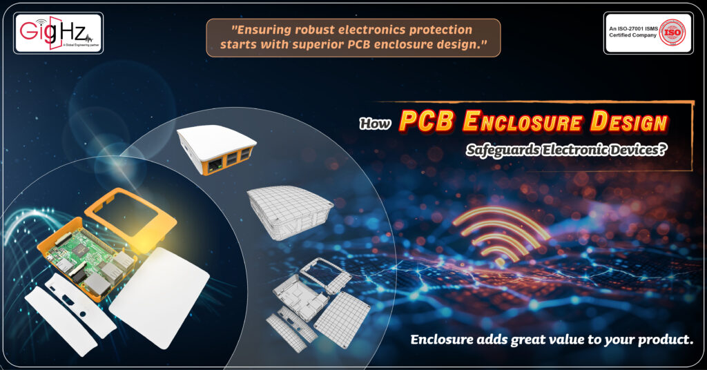
How PCB Enclosure Design Safeguards Electronic Devices?

PCB Enclosure Design  mechanical enclosure adds significant value to a PCB or electronic board by protecting it and enhancing its functionality. When a PCB is housed within a metal or plastic enclosure, it transforms into a finished product that is ready for the market. The primary application of a PCB enclosure is to safeguard the PCB from external environmental factors, ensuring it meets the required IP rating (Ingress Protection) standards. This protection is crucial for ensuring longevity and reliability, particularly in harsh environments. In addition to its protective role, the enclosure also adds aesthetic value to the product, providing a more polished and professional appearance. For any PCB to be sold as a standalone product, enclosing it in a durable plastic or sheet metal casing is essential, not only for protection but also to enhance its market appeal and perceived quality. So, what the pcb enclosure design intent entails? It reflects your company brand, product, and design intent. Let’s consider, designing the enclosure for Raspberry Pi 4 Model B with 1GB RAM, for Automotive Infotainment system, for your good understanding about enclosure design. Do you think what will be the design considerations, Here is the list of points you should consider during the electronics enclosure design techno-commercial decision-making process, Products Aesthetics Production volumes or market sizes Product Application Project Budget Cost Constraints Let’s dig in! How PCB Enclosure Design Safeguards Electronic Devices? Environmental Protection: These enclosures shield internal electronic components, like the PCB, from environmental threats like dust, moisture, chemicals, and temperature variations. This defense is crucial in preventing electronics from damage caused by harsh conditions. Physical Safeguarding: Enclosures provide a barrier against physical harm, impacts, and vibrations that could harm delicate PCBs and electronic parts, particularly in industrial and outdoor settings. EMI/RFI Protection: Many PCB enclosures feature shielding materials to safeguard sensitive electronics from electromagnetic interference (EMI) or radio frequency interference (RFI), ensuring signal integrity and blocking external electromagnetic disturbances. Enhanced Safety: By preventing accidental contact with electrical components, enclosures boost user and maintenance staff safety, mitigating risks of electric shock or fire incidents. Efficient Organization: Incorporating mounting rails, brackets, and cable management options, PCB enclosures streamline the arrangement and security of electronic components, maximizing space utilization and simplifying maintenance tasks. Tailored Configurability: Modular or customizable PCB enclosures can adapt to diverse PCB sizes, form factors, and additional elements like connectors, switches, displays, and cooling setups. Effective Cooling Solutions: Through ventilation slots, fans, or heat sinks, enclosures dissipate heat generated by electronics, ensuring optimal operating temperatures and averting overheating issues. Sealed Integrity: For applications demanding environmental sealing, PCB enclosures can integrate gaskets, O-rings, or other seals to uphold airtight or watertight properties, vital for outdoor or marine environments. Flexible Mounting: PCB enclosures can cater to various mounting preferences, ranging from wall, rack, to DIN rail mounting options, tailored to specific application requirements. Material Diversity: Enclosure materials like plastic, metal (such as aluminum or steel), and fiberglass offer distinct benefits in terms of durability, weight, and resistance to corrosion, providing choices for varied operational needs. Our journey of designing the enclosure Automotive Infotainment System integrating the Raspberry Pi 4 Model B (1GB RAM) When approaching the design of a PCB enclosure for an Automotive Infotainment System integrating the Raspberry Pi 4 Model B (1GB RAM), we employ a meticulous technical strategy tailored to meet the stringent requirements of the automotive industry. Here’s how we navigate the technical intricacies for this specialized application: Comprehensive Project Requirements Analysis: We conduct a detailed assessment of the Automotive Infotainment System specifications, focusing on temperature tolerances, vibration resistance, EMI shielding, and compliance with automotive safety standards to ensure optimal performance. Careful Selection of Enclosure Materials: We opt for automotive-grade ABS plastic or similar materials renowned for their impact resistance, durability, and chemical compatibility, guaranteeing longevity and robust protection in challenging automotive environments. Precision in Dimensional Accuracy and Form Factor: We meticulously design the enclosure to precisely accommodate the Raspberry Pi 4 Model B board and associated peripherals, considering space constraints within the vehicle and ensuring seamless integration with standard mounting systems. Implementation of Advanced Environmental Sealing: We incorporate sophisticated sealing techniques such as gaskets, O-rings, and IP-rated protection to safeguard the internal electronics from moisture, dust, and other external contaminants prevalent in automotive scenarios. Efficient Thermal Management Solutions: We incorporate advanced thermal management solutions, such as heat sinks, thermal pads, and active cooling systems, to effectively dissipate the heat generated by the Raspberry Pi 4 components. This ensures the board maintains optimal operating temperatures, preventing overheating and ensuring sustained performance during extended use. By implementing these solutions, we help enhance the longevity and reliability of your Raspberry Pi 4-based projects. Optimization of Component Layout: We strategically arrange the Raspberry Pi 4 board, connectors, and peripheral interfaces within the enclosure to maximize space utilization, simplify maintenance procedures, and streamline cable routing for enhanced connectivity efficiency. Robust Cable Management Techniques: We implement advanced cable management practices, including cable routing channels, strain relief features, and cable tie mounts, to organize wiring harnesses systematically, minimize signal interference, and ensure secure connections across the system. Adherence to Safety Compliance Standards: We ensure strict compliance with automotive safety regulations such as ISO 26262 for functional safety and EMC directives for electromagnetic compatibility, ensuring the reliability and regulatory alignment of the infotainment system in automotive environments. Selection of Durable Materials for Longevity: We carefully choose high-quality enclosure materials such as ABS plastic known for its exceptional mechanical strength, chemical resistance, and UV stability, guaranteeing the enclosure’s durability and resilience to environmental challenges in automotive applications. By applying these technical principles within our PCB enclosure design process for the Automotive Infotainment System featuring the Raspberry Pi 4 Model B (1GB RAM), we create a reliable and optimized solution that safeguards the critical electronics and enhances the overall user experience within automotive setting. Our Key Services PLASTIC ENCLOSURE DESIGN GigHz offers tailored enclosure design services for both plastic and sheet metal enclosures, catering to various industries such as Automotive Electronics, Consumer Electronics, IoT,

How PCB Enclosure Design Safeguards Electronic Devices? Read More »

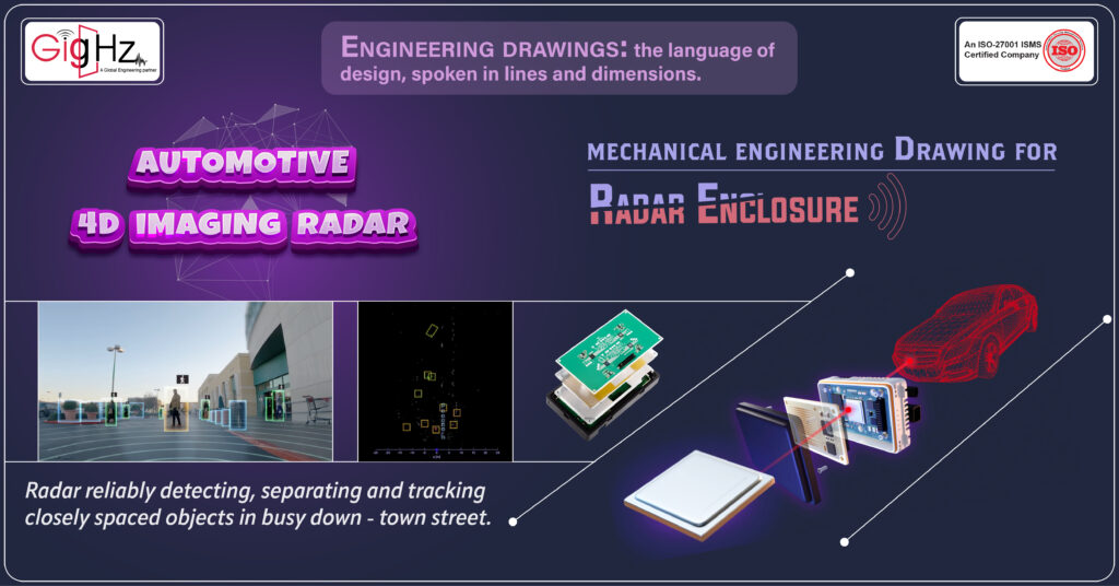
Balanced mechanical engineering Drawing for Radar Enclosure

Mechanical  Engineering Drawing Think of the Radar Enclosure in your car’s ADAS system as a superhero cape for the radar—shielding its critical components from the elements, whether it’s rain, dust, or extreme temperature shifts. This protective barrier keeps the radar performing at its peak, ensuring long-term reliability and durability. Now, why is this so awesome? With the Radar Enclosure guarding the radar gear, the system becomes a precision instrument, spotting objects with accuracy and clarity. It’s like having a watchful eye on the road, alert to every movement and obstacle, making your driving experience not just safer but smarter too. So, next time you drive, remember that hidden within your car’s ADAS setup is this quiet champion – the Radar Enclosure, silently ensuring that your radar system performs at its peak, keeping you safe and sound on the road. How cool is that? Now, let’s talk about the cool stuff – the Automotive 4D Imaging Radar. This radar system is like having eyes all around your vehicle, using four dimensions (that’s 3D space plus time) to give you a real-time view of what’s happening on the road. It’s the secret sauce behind features like adaptive cruise control, dodging accidents, and even paving the way for cars that can drive themselves by keeping an eagle eye on what’s going on around them. Let’s showcase our journey of creating the mechanical engineering drawing for the ADAS Radar enclosure that we developed, Basics Components of an Engineering Drawing Basics for Engineering Drawing involves generating ideas and concepts for creating technical drawings that accurately represent the design and function of a machine or component. This process often includes exploring different types of views such as isometric, orthogonal, and top views to show the shape and dimensions of the object. Orthographic projection is commonly used to represent the object’s physical boundaries and design intent. Furthermore, section views may be used to showcase internal features and part numbers. The use of dimensioning and tolerances ensures that the manufacturing drawings meet the requirements of an engineering part. CAD software plays a significant role in creating accurate drawings with extension lines, arrowheads, and title blocks that provide information about the drawing. When brainstorming for engineering drawing, it is essential to consider the different types of lines that are used to represent various features such as hidden lines and dimension lines. Multiview drawings may be used to show the object from different angles, including the front view and top view. The cutting plane technique can be applied to create section views that reveal the internal components of the machine. Moreover, drawings often include a scale to ensure that the dimensions accurately represent the size of the object. Drawing standards dictate the format and layout of the drawing, including the placement of the title block and the drawing number for identification purposes. Challenges we Faced The client has given us the responsibility of transforming their Radar PCB Enclosure (3D CAD model) into accurate 2D engineering drawings tailored for manufacturing purposes.  The challenges we faced are, Software Compatibility: Involves effectively navigating and harmonizing multiple versions of CAD software to facilitate seamless collaboration among team members working on the project. By ensuring that everyone can work cohesively regardless of the specific CAD tools they use, this aspect fosters efficient communication and workflow integration within the project. Precision and Accuracy: Focuses on the critical task of translating detailed 3D models into precise and faithful 2D representations. This process demands meticulous attention to detail to capture all dimensions, angles, and features accurately, ensuring that the resulting engineering drawings are a true reflection of the original design intent and are ready for manufacturing without any discrepancies. Regulatory Compliance: Encompasses the essential aspect of adhering to established industry standards, guidelines, and regulations during the creation of engineering drawings. By following these compliance requirements meticulously, the drawings produced align with safety, quality, and legal norms, thus guaranteeing that the final product meets all necessary certifications and approvals. Time Constraints: Represents the challenge of producing high-quality engineering drawings within a restricted timeframe. This factor necessitates efficient time management, prioritization of tasks, and streamlined processes to meet project deadlines without compromising on the accuracy and completeness of the drawings, ensuring timely delivery and project success. Complex Geometries: Involves the intricate task of clearly and succinctly dimensioning complex assemblies and components within the engineering drawings. This demands a deep understanding of geometric principles, spatial relationships, and technical specifications to accurately represent the intricacies of the design in a comprehensible manner, enabling effective communication and manufacturing of the final product. Balanced mechanical engineering Drawing for Radar Enclosure Input Analysis Upon analyzing the inputs provided by the client, it is evident that they have shared 3D models encompassing both individual enclosure parts and the assembly. The breakdown includes an Enclosure Assembly file (A1) along with specific parts such as the Top Casing (P1), Bottom Casing (P2), Switch (P3), Switch Holder (P4), and Light Pipe (P5). In terms of requirements, the client has outlined the desired formats for the drawing files and outputs to align with their needs. Specifically, for the Part 3D Model, the client expects the following deliverables: a Part file in sldprt format, a STEP file in STEP AP214 format, drawings in DXF and PDF formats, a Drawing File in slddrw format, and a PNG file showcasing the 3D model. This comprehensive analysis sets the stage for meeting the client’s expectations and ensuring that the resulting engineering drawings are crafted precisely as per their specifications and preferences. Work Outline Identify Views and Sections: We kick off by identifying the crucial views and sections needed to accurately portray the 3D models in our 2D drawings. This helps us ensure that every angle, detail, and aspect is captured for a comprehensive representation. Create Orthographic Views: We then dive into creating precise orthographic views, laying down a clear and structured depiction of the parts and assembly. These views form the foundation for further detailing and annotation, guiding our design process. Generate Section

Balanced mechanical engineering Drawing for Radar Enclosure Read More »

Behind the Scenes: Our Recent Mechanical Enclosure Design Journey

Mechanical Enclosure design Imagine a team of radar sensors working in perfect sync to keep you safe on the road—that’s the power of a cascaded radar sensor module! By strategically positioning multiple radar sensors around the vehicle, this system enhances your car’s ability to “see” its surroundings with greater accuracy, allowing for faster reactions to potential hazards and a safer driving experience. It’s like having extra sets of eyes that work together to ensure you stay safe by detecting obstacles, other vehicles, and pedestrians more accurately. This smart technology is all about making your driving experience smoother and safer, thanks to the teamwork of these radar sensors watching out for you at every turn. Now, we are excited to share that we have recently completed the mechanical enclosure design for the cascaded radar sensor module for ADAS application and would love to discuss our experience with you. Let’s dig into our journey, Ideas for Cascaded Radar Sensor Module Enclosure Design Automotive Cascaded Radar Sensor Module is a crucial component in modern vehicles for ensuring safety and enhancing driving experience. The prototype is first developed using sheet metal or injection molding, with connectors integrated into the enclosure. We ensure that the enclosure meets the EMI requirements and protects the electronic products inside. We offer enclosure design services that cater to both plastic enclosures and metal enclosures, providing rugged and durable solutions. The bottom of the enclosure is designed to accommodate the pcb and other electronic components, with a focus on mechanical engineering to ensure a sturdy device. When it comes to product development, our engineering services also include injection molding, creating custom enclosures tailored to the device’s needs. The design must consider the detailed mechanical aspects of the enclosure to provide optimal protection for the electronic components within. Our expertise in electronic enclosure design ensures that the enclosure is not only functional but also aesthetically pleasing. We specialize in designing custom enclosures with necessary features and specifications, utilizing tools such as injection molding and sheet metal enclosures to bring innovative solutions to the automotive industry. Complications we faced in our design Our client presented us with a daunting task: Designing a protective casing for their portable radar circuit board. The details provided brought forth a considerable design challenge that we were eager to tackle head-on. Framing the enclosure design around the radar antenna specifications was crucial for ensuring optimal functionality and fit. However, the Radome parameters remained unspecified, adding an additional layer of complexity to the project. Selecting the appropriate material for the Radome became a pivotal decision to safeguard the circuit board effectively while maintaining performance standards. Additionally, accommodating through-hole components within the PCB added another dimension to the design process, requiring meticulous planning and precision execution to meet the client’s requirements. Behind the Scenes: Our Recent Mechanical Enclosure Design Journey Our process is rooted in understanding the radar antenna parameters and translating them into robust enclosure solutions that ensure optimal performance and longevity. We split it as the Concept Phase and Design phase, In the Concept Phase of our project, we outlined the key requirements that guided our design process: They share info about the 3D step file for the PCB and a document contain additional details. We collect all these details and organize them in a step-by-step order. Radome Design Study: We delved into the intricacies of Radome design to align closely with the characteristics of the radar antenna. The condition for material selection as per the inputs are Enclosure material based on the radar antenna characteristics. Following our Exploration, the enclosure design for radar antennas is influenced by these parameters Material selection Radome wall thickness Antenna to Radome Distance  Manufacturing Process Selection: We carefully selected manufacturing processes that prioritized precision, repeatability, cost-efficiency, and rapid production cycles. Sketching with Detail: We translated conceptual ideas into detailed sketches that captured the essence of the enclosure design. Our Approach: Radar Antenna Enclosure Design Study Our design process kicked off with an in-depth study of radar antenna characteristics, informing critical decisions such as: Material Selection: Opting for materials like Polycarbonate based on radar antenna parameters. Radome Wall Thickness: Determining the optimal thickness, such as 1.1625 mm, to strike a balance between structural integrity and weight. Antenna to Radome Distance: Establishing the ideal distance of 1.875 mm to enhance signal transmission and reception efficiency. Design Phase – CAD Model Development As we transitioned into the design phase, our focus shifted towards CAD model development, involving: Outline Design and Optimization: Iteratively refining the design for improved efficiency and functionality. Aesthetics Improvement: Enhancing the visual appeal and user-friendliness of the enclosure. Final CAD Model: Crafting a detailed CAD model measuring 132.4mm x 103.34mm x 29.07mm, presented in both isometric and exploded views to allow for comprehensive evaluation and feedback. Our commitment to excellence extends to the manufacturing process selection, where we prioritize tight tolerances, part-to-part repeatability, cost-efficiency, and swift cycle times. By adhering to these standards, we ensure the seamless production of enclosures that meet and exceed industry benchmarks. Why we Do? Moreover, the research, thought, and innovation invested in the concept design phase serve as the foundation for the detailed design and development stages. Each idea generated and refined during this phase contributes significantly to the overall success and market viability of the final product. We challenge our MCAD capabilities with Automotive Industry to keep your time and cost in control with human touch quality Our Memorable Achievement: Engineering as a Service (EaaS) You know, as the need for advanced and integrated engineering solutions keeps soaring, our Engineering as a Service (EaaS) are really stepping up the game. We’re harnessing the power of ECAD, MCAD, and Analysis & Simulation. This gives us a great position to be frontrunners in this industry. What’s really cool is that we offer a full package, covering every single step of the engineering process. And honestly, it’s this kind of approach that’s going to shape the future of our engineering. It’s exciting stuff! Conclusion Through an intensive

Behind the Scenes: Our Recent Mechanical Enclosure Design Journey Read More »

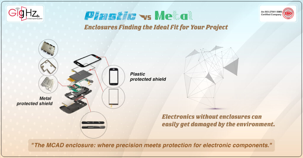
Plastic Vs Metal Enclosures Finding the Ideal Fit for Your Project

Plastic Vs Metal Enclosures You know how important mobile phones are in our lives today, right? From kids to grown-ups, we all rely so much on them. But have you ever thought about the unsung hero that keeps our phones safe inside? That hero is the mechanical enclosure. It’s like a silent protector that shields the delicate insides of our phones from everyday bumps, spills, and other risks. Without this invisible shield, our phones wouldn’t last long or work as well as they do. So, next time you use your phone, remember the little enclosure that’s silently working hard to keep it running smoothly for you! Enclosures shield gadgets from harm, making them last longer. They help keep electronics neat and make repairs easier. Enclosures prevent accidents like shocks or short circuits, keeping users safe. Electronics without enclosures can easily get damaged by the environment. Devices can break easily without protection from things like water or heat. Unprotected components can be dangerous, causing shocks or fires that harm people and property. Here, we should consider which type of enclosure is best suited. When designing the enclosure, let’s compare plastic enclosure versus a metal enclosure. Plastic Enclosure To understand the significance of plastic enclosures, it’s essential to delve into their applications and benefits, Let’s dive into how plastic enclosures are making a big splash in the automotive world, especially when it comes to electric vehicles (EVs). Think of EV battery packs as the powerhouse of electric cars. They’re like the heart, pumping energy to make the car zoom around. But just like any heart, it needs protection and care, which is where plastic enclosures come into play. Why Plastic Enclosures Are a Big Deal for EV Battery Packs? Imagine driving your EV on a rainy day or on a dusty road. You’d want your EV’s heart, the battery pack, to be safe from water, dust, or any bumps along the way, right? That’s exactly what plastic enclosures do. They wrap around the battery cells like a protective shield, keeping them safe from environment. Batteries can get pretty hot, especially when you’re charging them up or pushing your car to its limits. If they get too hot, it’s not good news. Plastic enclosures can be designed to work with cooling systems, making sure the battery stays at a happy temperature. It’s like having a personal cooling fan, ensuring things don’t overheat. In the world of EVs, every pound matters. Lighter cars can travel further on a single charge, making weight a big deal. Plastics are much lighter than metals, which means using plastic enclosures can help shave off some weight. This leads to a more efficient ride without skimping on safety or durability. One of the coolest things about plastic is how versatile it is. You can mold it into almost any shape, which is perfect for customizing battery pack enclosures to fit snugly into any car design. This means more room for other important stuff or even bigger battery packs for a longer ride. As we all aim for a greener planet, using recyclable and biodegradable plastics for these enclosures aligns perfectly with the eco-friendly essence of electric vehicles. It’s about moving forward not just in technology but in sustainability too. Pros of Plastic Enclosure Cost One of the primary benefits of opting for plastic over metal is the cost aspect. Materials and production processes for plastic tend to be less expensive, leading to a reduction in the overall cost of the finished product. Weight Plastic also has the upper hand when it comes to weight. It’s generally lighter than metal, which can be particularly advantageous in sectors such as transportation, where reducing component weight is crucial for enhancing fuel efficiency. Insulating Properties Another advantage of choosing plastic is its insulating properties. Unlike metal, plastic does not conduct heat or electricity well, making it a safer option for applications that may come into contact with heat sources or human touch, thereby minimizing the risk of burns or electrical shocks. Versatility Lastly, the versatility of plastic in terms of design is unparalleled. With the right mold, plastic can be shaped into virtually any form imaginable, offering immense flexibility in product design and customization. Cons of Plastic Enclosure When comparing plastic to metal components, a few notable disadvantages of plastics include their strength limitations, higher minimum order quantity (MOQ) for mold setup cost justification, and the necessity of molds for production. Physical Stress While plastics can be engineered to possess impressive strength characteristics, they generally fall short in withstanding physical stresses to the same extent as metals within a similar cost range. Minimum Order Quantity (MOQ) Moreover, the MOQ required to offset the initial investment for mold setup in plastic manufacturing is typically higher, often around 250 units, compared to some metal processes that can accommodate small quantities of one or two parts.  It’s fascinating to see how something as seemingly simple as a plastic enclosure can play such a vital role in the future of automotive design and innovation. Metal Enclosure Let’s talk about how metal enclosures play a crucial role in the automotive world, especially when it comes to protecting sensitive electronic components inside vehicles like control units and sensors. Why Metal Enclosures Matter in Cars  Metal Enclosure act like shields, protecting electronic parts from things like water, dust, and temperature changes. This helps keep the important car systems safe and working well. They help make sure the car’s electronics work without any problems by reducing disruptive signals. This is really important to avoid any glitches or communication issues. Metal enclosures are tough and can handle bumps and vibrations on the road. They keep everything inside safe and secure, no matter how rough the ride gets. When things get hot, metal enclosures help take away extra heat from electronic devices. By managing temperatures, they prevent things from getting too hot and help electronics last longer. Metal Enclosures not only protect electronics but also make sure that all the data stays

Plastic Vs Metal Enclosures Finding the Ideal Fit for Your Project Read More »

5 Procedures to Design Electronic Product Enclosure

Electronic Product Enclosure Giving a cheerful welcome to the readers with smiles! Have you come across the term “shelter” and its significance, dear readers? I believe that every living thing requires a protective shelter. Have you all heard about nests? Nests are not always made by females. Among ‘weaver birds’, it is the duty of males for protective covering to make nests for females so that they can lay eggs. Similarly, in today’s advancing electronic landscape, every electronic device requires a protective covering known as an “Enclosure.” MCAD Enclosure is basically about designing protective coverings for electronic gadgets using special software. It’s like giving these devices a sturdy home to keep them safe and working well. It’s all about making sure your electronics stay happy and healthy in their little homes! To help you grasp the concept of enclosure design, we’ll walk you through our experience of creating the enclosure for the Outdoor Router Waterproof Enclosure. We followed standard procedures to ensure a robust and effective design. Let’s look closer! Before Design: Understanding Product Requirements Before Design: Understanding Product, Requirements is a crucial step in the product development process. Whether you are working on a hardware product or an electronics project, knowing the requirements for the enclosure design is key. Factors such as the weight of the product, the aesthetics of the design, and the corrosion resistance of the materials used all play a role in determining the right type of enclosure to use. One option is a metal enclosure made of alloy or sheet metal. Another choice is a plastic enclosure created through injection molding. Both options have their advantages and disadvantages, depending on the specific needs of the project. Custom enclosures can also be designed to fit the specific dimensions and requirements of the electronic components inside the enclosure. Before diving into the mechanical design and creating a 3d model of the enclosure, it is important to understand the functionality and limitations of the enclosure design. This includes considering factors such as cutouts for circuit boards, fasteners for securing components, and the manufacturing process for the enclosure itself. By taking the time to fully comprehend the requirements of the electronic enclosure, you can ensure a successful and efficient design process. Exploring the Essentials Before Designing Our Electronic Design Product Hey there! Before diving into the nitty-gritty of designing your product, it’s crucial to lay down the groundwork by understanding a few key aspects. Let’s take a closer look at what you need to consider: Short Description of Product Functionality: First things first, we outline a brief description of what our product will do. This summary sets the stage for the design process and helps keep the end goal in focus. Ideas for Exterior Appearance: Next up, we brainstorm some ideas for the external appearance of our product. Visualizing the outer shell can inspire the design direction and appeal to our target audience. Customer Interaction Features: Then, considering how our customers will interact with the product. Then, we think about connectors, switch buttons, and any other interface elements that make using the product a seamless experience. Aesthetic Vision: Envision the final aesthetic of our product, including color schemes, textures, and overall visual appeal. Crafting a captivating design can elevate the product’s perceived value. Operating Environment: We consider the environment in which our product will be used or stored. Understanding the operating conditions helps tailor the design for durability and performance. Compliance with Standards: Listing out any standards our product needs to meet, such as UL, FCC, or other industry-specific certifications. Ensuring compliance is essential for market acceptance and legal requirements. Design Tolerances: Defining the required tolerances for our design. Precision is key to ensuring functionality and compatibility with other components. IP Rating Consideration: We specify the IP rating requirements, like IP31, to determine the product’s protection against dust and moisture. This rating impacts where and how the product can be used. By addressing these points early on, we set a solid foundation for the design process and pave the way for creating a successful and user-centered product. Now, let’s bring your vision to life by incorporating these essential elements into your product design journey! 5 procedures to design electronic product enclosure Crafting the Design for an Outdoor Router Waterproof Enclosure Embarking on the journey of mechanical enclosure design, by designing an Outdoor Router Waterproof Enclosure requires meticulous attention to detail and a seamless blend of technical precision and creative vision. Let’s tailor the content above to showcase the application in designing this specific enclosure: Defining Model Requirements for the Enclosure: In designing the Outdoor Router Waterproof Enclosure, we meticulously outline the model requirements to accommodate essential components such as circuit boards, antennas, and power supply units. Each element is strategically positioned to optimize functionality and ensure a compact yet efficient design. Precision Internal Component Modeling with Tolerance Consideration: Within the enclosure, internal components are modeled with utmost precision, taking tolerance into account. By understanding how these components may vary, we design with exacting detail to guarantee a perfect fit and seamless integration, enhancing the enclosure’s performance and longevity. Structural Integrity through Rough Shell Construction: The rough shell of the enclosure is crafted with uniform thickness to provide structural integrity and durability. This foundational structure not only shields the internal components from external elements but also sets the stage for further refinement, ensuring a robust and reliable end product. Thoughtful Cutouts for Connectors Openings Reinforcing Support with Ribs and Component Holders: Incorporating cutouts for connectors, LED indicators, and other openings is a key aspect of the design process. These strategic openings not only facilitate user interaction but also enhance the aesthetic appeal of the enclosure, striking a balance between functionality and visual appeal. To fortify the internal components within the enclosure, support ribs and holders are strategically placed. These structural features provide stability and security, safeguarding the components against external forces and environmental conditions, thereby ensuring the longevity and efficiency of the enclosure. By weaving together technical expertise with

5 Procedures to Design Electronic Product Enclosure Read More »

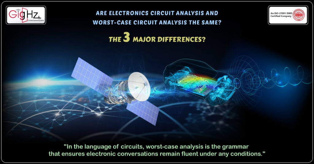
Are electronics circuit analysis and worst-case circuit analysis the same? the 3 major differences

Worst Case Circuit Analysis “Have you ever considered how we would convey our thoughts to each other’s without communication on any given day?” It’s true, Communication is the key to connecting with each other in this fast-paced world. Category : Published Date : Category : Published Date : Category : Published Date : Whether it’s the simplicity of a landline phone or the versatility of a smartphone, both devices have contributed to the evolution of communication, enhancing our ability to stay in touch and share our lives with others. “In the same way, the electronics world also requires communication between devices. How can we determine if they are effectively communicating with each other?” Yes, “Its through, when we analyse them, various types of analysis related to electronics come into play, including Electronics Circuit Analysis and Worst-Case Circuit Analysis(wcca).” Lets see the electronics circuit analysis and worst-case circuit analysis are the same? “Now, let’s immerse ourselves in it!” Exploring Electronic Circuit Analysis and Worst-Case Circuit Analysis. So, what does the Electronic Circuit Analysis entail? When it comes to electronic circuit analysis, it’s all about thoroughly examining and fine-tuning how circuits perform under normal conditions. This includes looking into things like signal integrity, voltage and current behavior, and making sure everything works as it should within the provided design limits. The goal here is to ensure that the circuit does what it’s supposed to do when operating under everyday circumstances, laying the groundwork for dependable and effective performance. In the automotive industry, electronic circuit analysis plays a pivotal role in the development of modern vehicles. We here utilize circuit analysis techniques to optimize the electrical systems within automobiles, ensuring efficient power distribution, reliable signal processing, and overall performance enhancement. By conducting comprehensive analysis and fine-tuning the circuits, we can guarantee the seamless operation of various electronic components such as infotainment systems, engine control units, and advanced driver-assistance systems (ADAS) under diverse driving conditions. This meticulous approach establishes a foundation for dependable and efficient performance, ultimately contributing to the safety and functionality of the vehicle. Upcoming to the worst-case circuit analysis, what it is? Ever wondered how electronic circuits are designed to withstand extreme conditions? That’s where worst-case circuit analysis (WCCA) comes in. It’s all about identifying potential risks and ensuring that the circuit functions even under the most extreme circumstances. This means taking into account things like component tolerances and environmental changes that could cause the circuit to perform poorly or fail. By testing the circuit under these extreme conditions, WCCA helps make sure that the design is strong and dependable. In the automotive industry, worst case circuit analysis is crucial for ensuring the reliability of electronic systems in vehicles. Let’s consider the electronic control unit (ECU) in a car. We use WCCA here, to analyze the ECU’s performance under extreme temperature variations, voltage fluctuations, and other adverse conditions that it might encounter during normal operation. This ensures that the ECU can function reliably in all scenarios, contributing to the overall safety and performance of the vehicle. Are Electronics circuit analysis and Worst-case circuit analysis the same? the 3 major differences Electronic circuit analysis and worst-case circuit analysis are interconnected, with the former addressing routine performance considerations and the latter specializing in extreme condition assessments to guarantee circuit resilience. 1.   Impact on Design Process Electronic Circuit Analysis Electronic Circuit Analysis plays a pivotal role in shaping the design process by aiming to maximize the performance and efficiency of the circuit under nominal operating conditions. This involves fine-tuning the circuit’s parameters and components to achieve optimal functionality within expected boundaries. The emphasis is on achieving the best possible performance while staying within the specified operational limits. Worst-Case Circuit Analysis Conversely, Worst-Case Circuit Analysis significantly influences the design process by prioritizing the enhancement of robustness and reliability under adverse scenarios. The analysis delves into identifying potential weak points in the circuit design and aims to fortify the system to withstand unforeseen challenges posed by component variations, environmental stressors, and extreme operating conditions. Real Time Application of the Analysis In the development of a sensor circuit for automotive applications, electronic circuit analysis ensures precise and reliable signal detection under regular driving conditions. This involves optimizing the circuit for accurate data acquisition within the expected range of temperature and voltage fluctuations commonly encountered in vehicle environments. In contrast, WCCA comes into play to evaluate the circuit’s resilience to extreme temperature variations, electrical disturbances, and unexpected operational scenarios, ensuring that the sensor maintains its functionality even in the harshest automotive conditions. 2. Application of Data and Risk Assessment Electronic Circuit Analysis Electronic Circuit Analysis plays a pivotal role in shaping the design process by aiming to maximize the performance and efficiency of the circuit under nominal operating conditions. This involves fine-tuning the circuit’s parameters and components to achieve optimal functionality within expected boundaries. The emphasis is on achieving the best possible performance while staying within the specified operational limits. Worst-Case Circuit Analysis Conversely, Worst-Case Circuit Analysis significantly influences the design process by prioritizing the enhancement of robustness and reliability under adverse scenarios. The analysis delves into identifying potential weak points in the circuit design and aims to fortify the system to withstand unforeseen challenges posed by component variations, environmental stressors, and extreme operating conditions. Real Time Application of the Analysis In the development of a sensor circuit for automotive applications, electronic circuit analysis ensures precise and reliable signal detection under regular driving conditions. This involves optimizing the circuit for accurate data acquisition within the expected range of temperature and voltage fluctuations commonly encountered in vehicle environments. In contrast, WCCA comes into play to evaluate the circuit’s resilience to extreme temperature variations, electrical disturbances, and unexpected operational scenarios, ensuring that the sensor maintains its functionality even in the harshest automotive conditions. 3. Validation and Testing Process Electronic Circuit Analysis Electronic Circuit Analysis often involves validation and testing processes focused on verifying the circuit’s performance under typical operating conditions. This includes utilizing simulations, modeling, and prototyping to validate the

Are electronics circuit analysis and worst-case circuit analysis the same? the 3 major differences Read More »

Keep Your Pcb Enclosure Cool Not Hot!

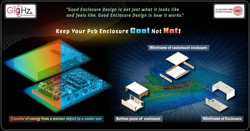
PCB Enclosure cool not Hot Welcome Back! Hope everything is going well. In everyday language, we often use the term ‘heat’ to describe warmth, but scientifically, heat is defined as the transfer of energy from a warmer object to a cooler one. PCB Enclosure Welcome Back! Hope everything is going well. In everyday language, we often use the term ‘heat’ to describe warmth, but scientifically, heat is defined as the transfer of energy from a warmer object to a cooler one. Category : Published Date : Category : Published Date : Category : Published Date : Heat is categorized into hot and cold based on this principle. Heat energy surrounds us in various forms, whether it’s in icebergs, volcanoes, electronic devices or even within our bodies. Every substance contains heat energy within its structure. The movement of tiny particles—atoms, molecules, or ions—in solids, liquids, and gases results in what we know as heat energy. This energy can be transmitted from one material to another due to temperature variations between the objects, which we refer to as heat flow. So, why here we are describing the heat, there is the reason behind these. When it comes to some PCB enclosures just can’t handle the heat, literally! Not all circuit boards crank out so much heat that they turn their enclosures into mini saunas, but when they do, it’s a problem. Without a proper way to let that heat out, your components could end up feeling the burn. There’s always a natural flow of heat from the hot bits to the cooler enclosure surface, but that flow needs an escape route to keep things in check. So, if you’re aiming to design a PCB enclosure that won’t cook your components, here are some savvy strategies to save the day. By making smart moves on both the enclosure and the PCB itself, you can kick that heat to the curb and maintain a chill vibe with the outside world. Smart Moves to Beat the Heat in Enclosure Key Info Electrical engineering and mechanical techniques can be used to combat the extreme temperatures inside an enclosure. Utilizing pcb heat dissipation techniques such as strategically placing heatsinks on hot components and incorporating heat exchange mechanisms can help move heat away from critical areas. Additionally, employing convection to circulate hot air and designing the enclosure air flow can improve overall heat dissipation. High thermal conductivity materials like aluminum can be utilized to spread heat and dissipate heat away from the enclosure. Advanced pcb design tools and design software can also aid in predicting and controlling heat generation and RF interference. By implementing these smart moves, the temperature inside the enclosure can be effectively managed to prevent hot components from becoming hot to touch. How do you spot this effect in your Enclosure? Some circuit boards can get really hot due to specific components like powerful processors, large FETs handling big currents, and high-current switching regulators that produce a lot of heat. When these components heat up, they not only warm the air around them but also increase the overall temperature of the circuit board. Without a case around the board, natural airflow helps cool things down a bit. However, when you enclose the board, trapped hot air can turn the enclosure into a heat trap. The enclosure can become too hot to touch, which is inconvenient if people need to handle your product. To identify when this heat buildup happens in your enclosure, you need to consider two main things: Touch Test: If the product becomes too hot to touch at around 45°C in a normal room setting, it’s a sign you’re reaching uncomfortable temperatures with only a small safety buffer of 25°C. Difference in Temperatures: Inside the enclosure, temperatures can be much higher than what you feel on the outside surface. Even with a metal enclosure, the difference between what you touch and the internal temperature could be significant, around 20 to 25°C. With insulating enclosures, this difference could be even greater. Applying Measures to reduce the heat in PCB              Keep your PCB Enclosure cool not Hot! When your enclosure gets sizzling hot and the internal temperature skyrockets, it’s all because the heat from the components can’t escape effectively. Instead of heating up something with high thermal mass, like a heatsink, these components end up just warming the air around them. While adding more copper to the PCB can help spread the heat a bit, it doesn’t solve the root cause of the oven effect, which stems from components heating the air around the board. To tackle this issue, you need to get creative with both the board and enclosure designs: Incorporate grills or air holes for natural convection Install fans on the enclosure for forced cooling Attach a sizeable heat sink on the board connected to the enclosure Integrate heatsink fins onto the enclosure surface Enable external airflow over the outer enclosure PCB thermal management is crucial in ensuring the reliability and performance of electronics housed in an electronic enclosure. With ICs and microcontrollers generating high heat during operation, it is important to keep the printed circuit board cool to prevent hotspots and potential damage. By incorporating cooling options such as heat sinks, thermal vias, and thermal pads into the pcb layout, heat can be effectively removed and dissipated. Additionally, increasing the surface area for heat dissipation by using an aluminum enclosure or adding heat pipes can further improve thermal management. However, if the enclosure is sealed, cooling options for sealed enclosures are limited. In such cases, heat exchangers or even an air conditioner may be necessary to prevent the enclosure design the heat load inside from increasing to a dangerous level. When designing an enclosure, it is important to consider the ambient temperature and the amount of heat produced by the electronics heatsink at the edge of the PCB can help to prevent heat from building up in one specific area, while thermal vias can help conduct the heat to be

Keep Your Pcb Enclosure Cool Not Hot! Read More »

Scroll to Top