Reduce Voltage Spikes in EV Boards With This Simple PDN Fix
- Posted On:
- September 30, 2025
- Category:
- Analysis & Simulation

As we all know that in any high-speed automotive electronics, a stable power rail is not negotiable at any cost.
Likewise, in one of our electric vehicle controller projects, PDN (power distribution network) optimization caused a major difference!
Because, a finalised design and weeks of frustrating debug sessions escalated to a major extent.
So, when your EV control systems are pushing the limits of switching speeds and load transients – even a 50 mV overshoot can trip protection circuits or corrupt data.
Moreover, at those tiny fluctuations every EV design team dreads—voltage instability, component resets, and failed compliance testing.
Apparently, we have seen this happening way too many times!
But in this case, we found a way to fix voltage spikes in EV boards without adding unnecessary complexity or cost.
As a result, an 85% reduction in transient overshoot and a board that passed its power integrity validation in one shot only.
The Issue of Voltage Instability in EV Electronics
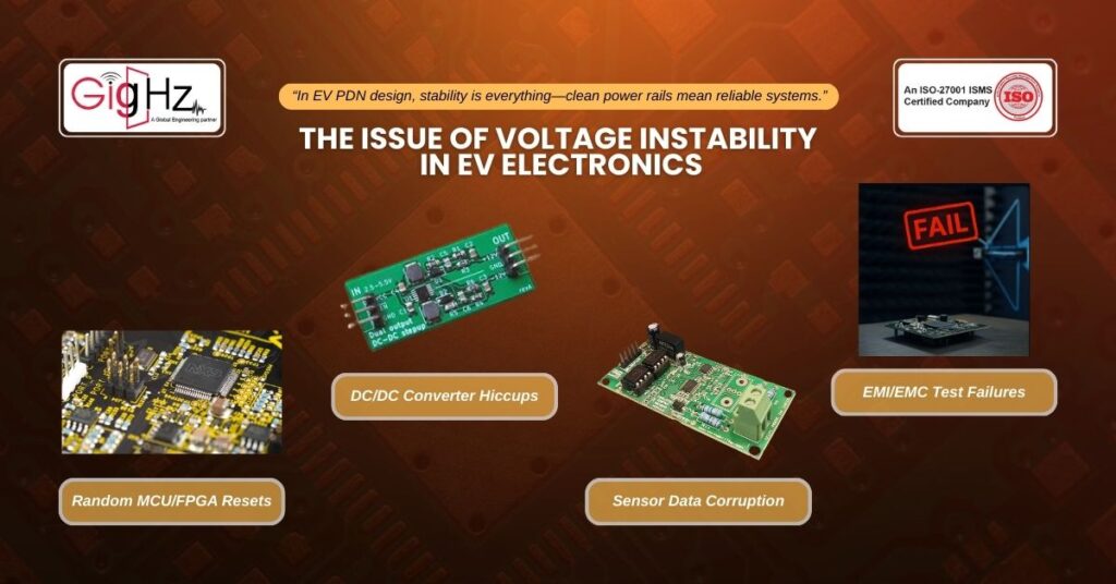
So, in PDN design for EV electronics, the problem isn’t just delivering enough current but it’s more about keeping that current clean and stable across a wide range of operating conditions.
Evidently, common symptoms of a weak PDN in automotive systems include:
- Random MCU or FPGA resets during load transients
- DC/DC converter hiccups at high acceleration or regenerative braking
- Sensor data corruption during RF transmission events
- EMI/EMC failures caused by rail noise coupling into high-speed nets
Plus, in our case, a single sensor fusion module kept failing under high-load transitions. Furthermore, our oscilloscope captured transient overshoots of up to 280 mV, well outside our ±100 mV target.
Root Causes of Power Instability

Likewise, we dug into the board’s PDN with both time-domain and frequency-domain tools. Also, what we found is a pattern we see all the time in power integrity issues in EV systems:
- Poor decoupling capacitor placement: Evidently, high-inductance mounting paths reduced high-frequency filtering.
- Inconsistent plane connectivity: Also, fragmented power planes increased loop impedance.
- Underdamped VRM output filter: Plus, oscillation-prone response to sudden load changes.
- Capacitor resonance peaks: Multiple capacitors with mismatched ESR values creating unwanted impedance peaks.
Targeted PDN Reinforcement
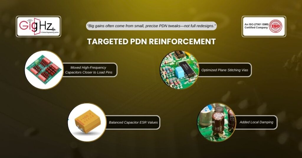
Now, we didn’t need to redesign the whole board—just reinforce the weakest links. So, here’s exactly what we changed:
Moved high-frequency ceramic capacitors closer to load pins
– Reduced mounting inductance from 1.2 nH to ~0.4 nH.
Optimized plane stitching vias
– Added low-inductance via pairs right at load capacitor sites.
Balanced capacitor ESR values
– Removed a redundant 47 µF tantalum with high ESR and replaced it with an MLCC that matched the impedance profile better.
Added local damping
– Introduced a small-value resistor in series with a key capacitor to suppress resonance peaks.
The Results
Before the fix:
- Peak overshoot: +280 mV
- Peak undershoot: –190 mV
- Recovery time: 8 µs
After the fix:
- Peak overshoot: +40 mV
- Peak undershoot: –35 mV
- Recovery time: 2 µs
Moreover, we didn’t just meet specifications! We also surpassed it, giving the system margin for temperature shifts and aging.
Lessons Learned: PDN Best Practices for EV PCBs
So, if you are also similarly struggling with voltage instability EV PCB fix challenges, here are the top takeaways from our project:
1. Treat Inductance as Your First Priority
- Every extra millimeter between a decoupling cap and the load adds inductance. Route as if every nanohenry matters—because at high speeds, it does.
2. Match Capacitors to Frequency Ranges
- Use small-value MLCCs for high-frequency noise, mid-range ceramics for mid-band stability, and bulk electrolytics for low-frequency load swings.
3. Avoid Plane Fragmentation
- Split planes are like speed bumps for current flow. Keep power and ground planes continuous, and stitch aggressively between them.
4. Damping Beats Over-Filtering
- Adding more capacitance without controlling resonance is a trap. That’s why, use targeted damping to flatten impedance peaks instead of chasing them with more parts.
5. Simulate Before You Build
- Power integrity simulators can flag impedance peaks and transient weaknesses before layout is frozen. Consequently, it’s faster and cheaper than finding them on the bench.
Why This Matters Beyond the Lab
Finally, an unstable PDN in an EV isn’t just a lab headache, it’s a major safety and reliability risk. Evidently, a single missed transient can cause:
- Loss of critical sensor data during high-speed maneuvers
- Intermittent control unit resets in the middle of operation
- EMC test failures that delay certification by months
So, with automotive launch cycles under pressure, avoiding such pitfalls is mandatory.
Final Takeaway
Summing up, we have seen time and again that small, targeted PDN improvements can deliver huge stability gains without blowing up your BOM.
Likewise, by addressing just four key weaknesses, we turned a failing EV controller board into a stable, compliant design and cut overshoot by 85% and passed validation on the first try.
So, if your next EV project is facing unpredictable voltage behavior, don’t default to “more capacitance.” Instead, track down the real impedance issues and fix them at the source.
Because when your PDN is rock-solid, the rest of your system gets to focus on what it’s designed to do to drive forward.
Contact us today at – https://gighz.net/contact-us/and let our experts help you eliminate such issues.
Stuck in a loop of challenges? Always pick smart solution that works
Have you faced costly rework because 2D drawings skipped in MCAD workflows?
Effective way to prevent MCAD documentation errors recalls?
Please answer both poll questions before submitting.
Thank you for your response! 😊
Latest Post
Get Customized Engineering CAD Design Service

Book a Free Consultation Call
Partner with Gighz and bring your most innovative design concepts to life. Our engineering cad services accelerate development so you can focus on your big vision.