5 Questions most of the experts Asks About PCB Thermal Management
- Posted On:
- March 18, 2025
- Category:
- Analysis & Simulation

PCB Thermal Management System
Have you ever had a moment when everything you planned fell apart, but it taught you something valuable?
That’s what happened to us last year when we took on the most important project of our career.
As a CEO, every project teaches me something new.
One of the most valuable lessons came when we were working on an important project for an automotive client.
Everything seemed to be on track until we hit a problem: our thermal management system wasn’t working as expected.
As EVs strive for longer driving ranges, the batteries need to store more energy.
This means more power is drawn, leading to increased heat generation during both charging and discharging.
Managing this heat is crucial to avoid thermal runaway, where excessive heat could cause damage to the cells or even lead to fires.
The issue was serious.
If we couldn’t manage the heat properly, the design wouldn’t meet safety or performance standards.
In the end, we didn’t just fix the issue—we created a design that was even better than we’d planned.
In this section, I’ll be addressing five key questions regarding thermal management, specifically at the design and Printed Circuit Board levels.
These questions were compiled from our research by consolidating the most frequently asked queries from industry thought leaders.
I’m excited to share these insights with you in this blog,
5 Questions most of the experts Asks About PCB Thermal Management
1. How Do I Translate a Copper Area Requirement for Heat Dissipation into My Board Design?
When you receive a datasheet calling for a specific copper surface area for heat dissipation, it’s essential to understand how this translates to your actual board design.
Thermal management is about temperature deltas—the difference between the temperature at the heat source and the temperature at the heat sink.
Adding copper alone won’t help if the heat is at a steady state.
If the area is limited on your board, you can maximize the copper area in the available space by optimizing traces and using larger copper pours.
If necessary, you may also use power or ground planes with larger copper weights, which are effective for transient thermal excursions, although they are less beneficial for steady-state power dissipation.
In cases where the copper area is constrained, consider using techniques like thermal vias to enhance heat flow.
2. How Much Heat Does a Via Dissipate, and How Does Size and Fill Impact This?
Via technology plays a crucial role in heat dissipation.
Filled vias, especially copper-filled vias, offer the best thermal performance.
Copper is a good conductor of heat, and using filled vias helps to transfer heat from one side of the PCB to the other, reducing temperature gradients.
The size of the via matters, as larger vias can dissipate more heat, but they must be balanced with the overall design constraints, such as space and manufacturing limitations.
Standard vias can be filled with copper, epoxy, or silver, with copper-filled vias offering the best thermal performance. It’s essential to ensure that the vias are filled completely to avoid air gaps, which act as poor conductors of heat.
The best thermal vias are stitching vias with solid copper plugs that match the coefficient of thermal expansion (CTE) of the PCB material, ensuring minimal stress and optimal heat transfer.
3. Does Moving Heat to Internal Layers Help with Thermal Dissipation?
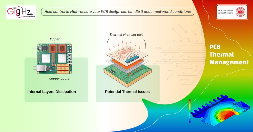
When considering the movement of heat within a PCB, adding copper layers internally may seem like a solution, but it’s not always the most effective.
For most steady-state thermal conditions, adding copper internally may not provide substantial benefits.
For transient thermal events, like those caused by sudden power spikes, internal copper can help to spread the heat across layers more evenly.
However, the main concern in most products is managing steady-state heat dissipation.
Adding external copper layers, especially copper pours, is typically more effective in dissipating heat because they help radiate heat through the PCB surface.
In cases where additional copper layers are considered, it’s essential to prototype and test the design, as simulation models may not always accurately predict real-world performance.
In some designs, adding copper internally may only improve performance for specific scenarios, such as in power electronics.
4. How Do I Identify Potential Thermal Issues Early in the Design?
Thermal issues can sometimes go unnoticed until later in the design process or after the product is in use.
A simple yet effective way to identify potential thermal issues is to conduct a thermal chamber test with a prototype.
By monitoring the prototype’s temperature in various operational states, you can pinpoint areas where heat is accumulating and identify insufficient heat pathways.
Thermal chamber testing is invaluable in correlating simulations with real-world performance.
During these tests, you can assess whether the design meets thermal expectations and whether thermal vias or heat sinks are necessary.
This allows you to make informed design decisions early in the process, potentially saving costs and time later.
5. How Do I Translate Heat Dissipation Requirements into Actionable Design Parameters?
Latest Post
Get Customized Engineering CAD Design Service

Translating thermal management requirements into design parameters is often a challenge, as the data provided on a datasheet (e.g., power dissipation in watts) isn’t always enough.
The first step is understanding the system and environment in which the device will operate.
Often, thermal management is an iterative process: initial designs are tested in real-world conditions, and then adjustments are made based on performance.
A general approach to address thermal challenges:
- Lower power dissipation: Select components that use less power or operate at lower voltages.
- Improve heat transfer: Utilize thermal vias, heat sinks, or even external cooling systems to help transfer heat away from components.
- Constrain operating conditions: Consider software-controlled limits to reduce power dissipation during critical processes.
Thermal analysis should be an ongoing process, with prototyping used to validate assumptions. The goal is to prevent the components from exceeding their rated junction temperatures, which could lead to thermal runaway or failure.
Summary
Effective thermal management solutions are essential for ensuring the reliability of electronic components in high power applications.
The design of PCBs plays a crucial role in managing heat accumulation, as thermal resistance affects the amount of heat generated by power components.
Techniques such as conduction, convection, and the use of heat pipes or liquid cooling can significantly improve effective heat dissipation.
The length of the thermal path and the thermal conductivities of materials used are critical factors in designing a PCB that minimizes the risk of overheating.
“Solve Your Thermal Management Challenges Today!”
Efficient thermal management is the key to maximizing the performance and safety of your automotive PCBs.
Reach us at info@gighz.net for a free consultation and start improving your thermal designs today.
You’re just one click away from ensuring your designs are safe, efficient, and ready for the future!
Book a Free Consultation Call
Partner with Gighz and bring your most innovative design concepts to life. Our engineering cad services accelerate development so you can focus on your big vision.