There was this time when everyone in my team blamed the board for thermal imbalance.
However, upon intense inspection the board turned out to be just fine.
So, what went wrong exactly?
Actually, when our prototype failed during stress tests, we suspected the usual troublesome factor — classic PCB thermal issues.
But after redesigning twice, over dozens of sensors, and one long night with an IR camera, we found the real issue!
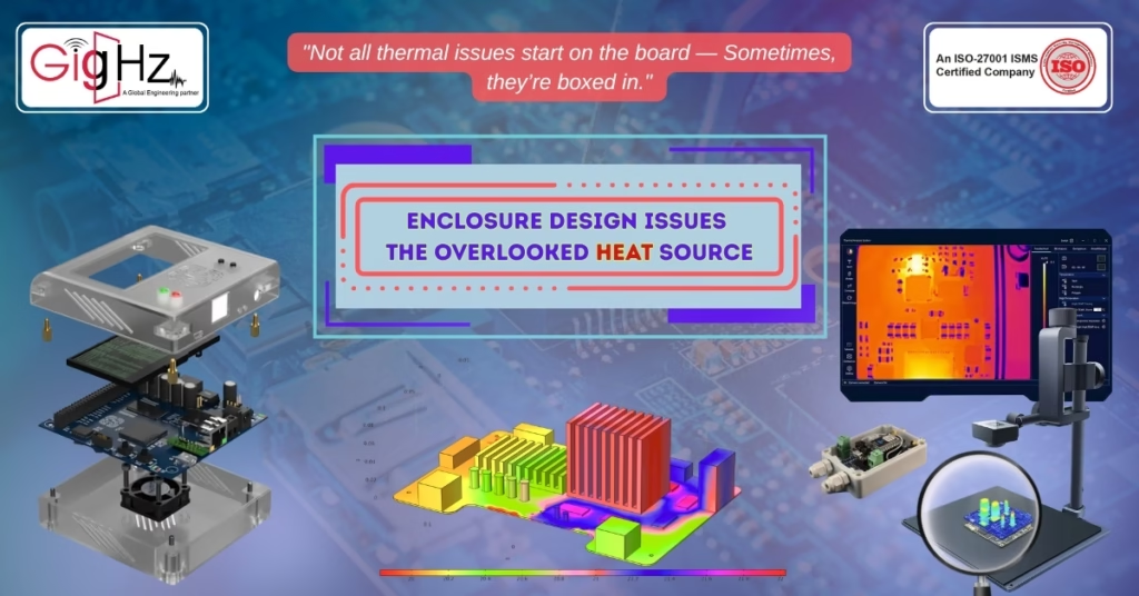
And that is, the enclosure was suffocating the board.
Likewise, it is one of the very critical enclosure design problems that exists till date.
It Wasn’t the PCB After All
Similarly, you spend weeks perfecting your thermal management in PCBs — wide copper pours, thermal vias, heatsinks, and perfect component spacing.
But what if none of that matters at all!
Whereas it’s the enclosure that traps the heat like a sealed box on a summer day?
Yes, that’s exactly what happened to us.
I particularly remember how we assured perfection of every aspect of the board’s cooling profile.
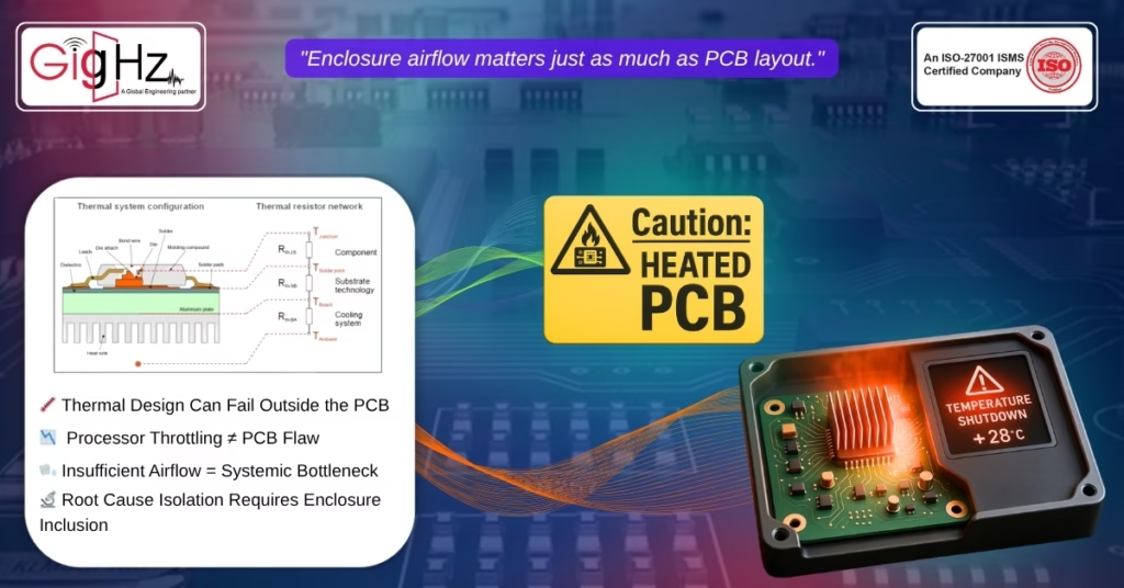
However, when we ran real-world tests inside the final casing, the temperature spiked by 28°C rapidly while the processor throttled. Consequently, power stages were immediately shut down without any delay.
Likewise, for us we focused on getting some aid from electronics cooling solutions… but no amount of tweaking the PCB helped.
And, that’s when we decided to inspect the enclosure.
How a Beautiful Enclosure Ruined Our Design
Now, the product we built was sleek and compact, with a precise edge-to-edge casing and minimal ventilation. So, what was the issue then?
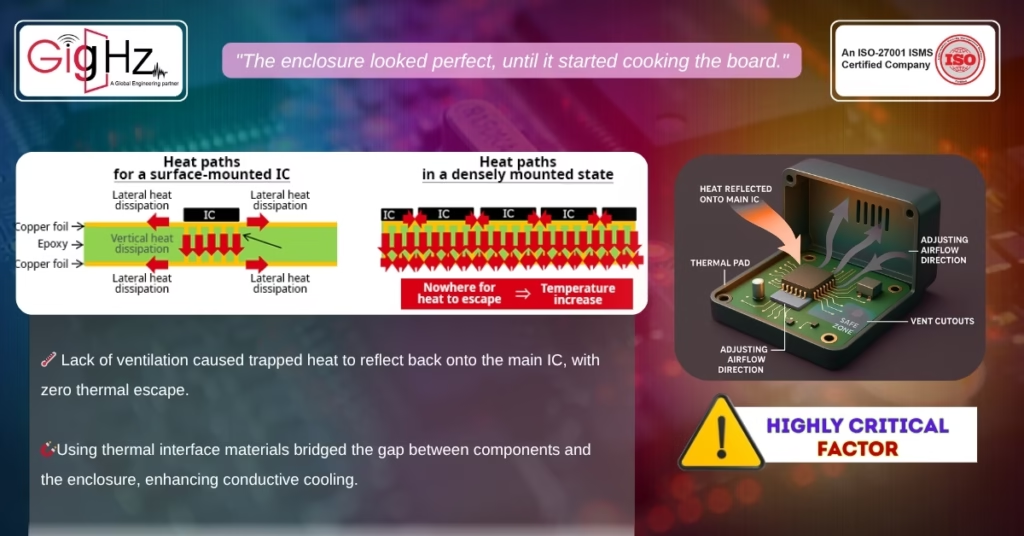
Well, it also blocked airflow to the voltage regulators, plus it reflected heat back onto the main IC – with zero thermal escape path.
Besides, with laser focus attention to thermal management in PCBs — We tried fixing it with heat sinks and copper fills. But there was no luck at all!
Only after redesigning the entire case by adding:
- Vent cutouts
- Adjusting Airflow Direction
- Using thermal pads
The temperature finally dropped into the safe range margins.
In a nutshell, the real issue was never about the design. Rather, it was one of the enclosure design problems which we never saw coming.
So, before blaming your PCBs again, look out for these early warning signs beforehand.
- Temperature spikes during enclosure testing: The board runs fine open-air but at times overheats inside the shell.
- Components derating even after thermal tuning: Despite all your efforts, parts will still shut down.
- No ventilation paths near VRMs/ICs: Apparently, critical heat zones get ignored in the enclosure layout.
- External casing feels excessively hot: A hot shell = trapped internal heat.
Even the most perfectly designed board can’t survive a poorly designed box.
Thermal Success Starts Beyond the Board

So, even if you are fighting such PCB thermal issues, then you need to take a pause.
Evidently, you must start thinking about electronics cooling solutions as a system-wide strategy — Not just a PCB-level fix!
Accordingly, here’s what we do now on every project since then:
- Thermal Simulate Early: Run performance simulations that not only includes the board but also the enclosure. Likewise, many modern CAD tools offer coupled ECAD-MCAD thermal simulations.
- Component Placement with Enclosure in Mind: Always, place heat-generating components where the enclosure supports dissipation & not where it blocks it.
- Use Thermal Interface Materials: Note that thermal pads, adhesives, and shielding can bridge the gap between PCB and the case. So, don’t overlook them. Likewise, you may utilize thermal simulation tools like ANSYS Icepak, SolidWorks Flow Simulation, or Fusion 360 with thermal extension to analyze enclosure-level heat behaviors. Moreover, these tools let you spot thermal bottlenecks and optimize your design while it’s still digital.
- Cross-Team Reviews: In the end, always have the mechanical and electrical teams do a full joint review. Because, half of the enclosure design problems start from teams working in isolation.
- Benchmark with Real Use Cases: Finally, initiate a test with the final enclosure early, under worst-case load scenarios. As a result, you will learn more in 30 minutes of testing than in 3 days of guesswork.
Finally, with these proven practices, we’ve avoided countless delays, rework, and late-stage redesigns.
Bottom Line
In order to sum up, thermal management in PCBs represents only one aspect of the overall reliability and performance equation.
So, don’t wait! Until your prototype starts melting up and discovers that enclosure design problems are sabotaging your product. Therefore, always develop and rely on your electronics cooling solutions extensively.
Because when thermal issues arise, they override even the most perfectly designed PCB.
Feel free to contact us at info@gighz.net and avail a free consultation call today.
Latest Post
Get Customized Engineering CAD Design Service

Book a Free Consultation Call
Partner with Gighz and bring your most innovative design concepts to life. Our engineering cad services accelerate development so you can focus on your big vision.