PCB Design Changes
Last-minute changes in PCB design can feel like a storm on a calm sea.
But through my personal experience,
I’ve learned that these challenges can be opportunities to refine and innovate, rather than obstacles to fear.
Over the years, however, I’ve developed a methodical approach to managing these last-minute changes that helps me keep projects on track without compromising quality.
Sometimes, making last-minute changes to your PCB design is unavoidable, especially just before sending it off to a manufacturer.
Whether it’s due to unavailable components, supply chain adjustments, or simple design errors, these changes often involve swapping components, rearranging traces, or modifying placements.
While design rules in your tools can flag some issues, not every potential problem gets caught—especially those related to Design for Manufacturing (DFM).
In some cases, even a functional design change might fail DFM checks, leading to delays in fabrication or assembly.
Slight adjustments made to accommodate supply chain constraints might inadvertently create manufacturing challenges if not thoroughly reviewed.
Here’s a look at how I’ve learned to handle these situations, ensuring that even when things change at the eleventh hour, my design stays on time and on point.
How to Handle Last-Minute PCB Design Changes on Time?
1. Assessing the Impact of Last-Minute Changes

The first step in handling any change, especially a last-minute one, is to evaluate its impact. When a change comes through—whether it’s a component swap or a slight modification to the layout—I take a moment to step back and ask, “How does this affect the design as a whole?”
I remember one instance where I had to swap a microcontroller last minute because the originally chosen part was out of stock.
The new component had different pin configurations and power requirements, which meant that my original layout needed significant adjustments.
What helped me in this situation was to look at the overall impact:
Is the change going to affect signal integrity, thermal management, or the power distribution network?
With this understanding, I was able to prioritize which areas of the design would need the most attention.
Key Takeaways:
- Component Footprints: Ensure that the new component fits into the available space and the footprints are correctly aligned.
- Thermal Considerations: If the new component generates more heat, it’s critical to run a thermal analysis to ensure the board will be able to handle the increased load.
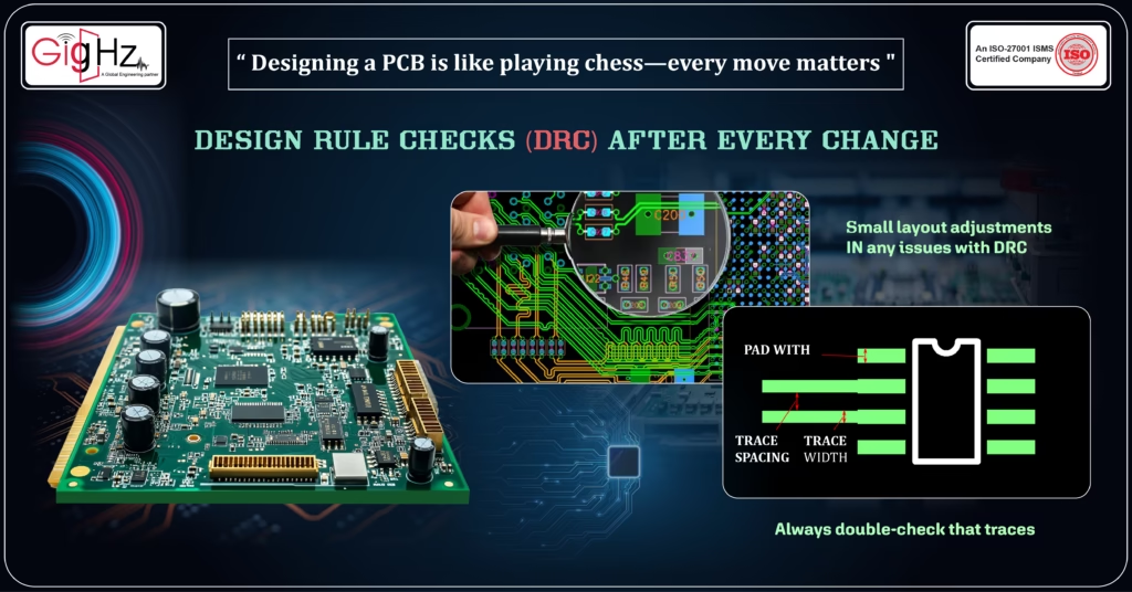
2. Running Design Rule Checks (DRC) After Every Change

After evaluating the impact, the next step I always take is to run Design Rule Checks (DRC). Early on in my career, I mistakenly thought that small layout tweaks wouldn’t cause any issues with DRC. But I quickly realized that even the smallest adjustments could violate clearance rules or affect trace width, leading to unexpected problems down the line. It was a valuable lesson in how every detail matters in design!
For instance, once I swapped out a component for one with a different package size, the trace width I had originally routed became too narrow. If I hadn’t run a DRC immediately after the change, I might have missed this, which would have caused problems during manufacturing.
Key Takeaways:
- Trace Width and Clearance: Always double-check that traces maintain the proper width and clearance to avoid shorts or signal integrity problems.
- Pad Size Adjustments: Pay special attention to pad size if you’ve swapped out a component, as a mismatch could lead to faulty soldering.
In my experience, running DRC checks after every change is a simple habit that saves me from headaches later in the process.
3. Performing Quick Simulations

One of the lessons I’ve learned over the years is that simulation is not just a tool for when you’re done with the design—it’s a tool to use during every stage, especially when changes are made. Whether it’s signal integrity or power integrity, I always run quick simulations after last-minute changes.
I recall a project where I had to change the routing of high-speed data lines just a week before the design deadline. Instead of pushing ahead without checking, I ran a signal integrity simulation.
This caught an issue with crosstalk that I would have missed otherwise, and I was able to reroute the traces to avoid signal degradation.
Key Takeaways:
Signal Integrity: For high-speed circuits, tools like HyperLynx or Ansys HFSS help to simulate signal behavior and detect issues like cross-talk or reflections.
Power Integrity: After changing power routing or adding new components, a power integrity simulation helps ensure there are no unexpected voltage drops or ground bounce.
Simulations are a powerful way to catch problems early on and prevent costly mistakes later.
4. Checking Design for Manufacturability (DFM)
As a designer, one of the most valuable lessons I’ve learned is that last-minute changes aren’t just about functionality—they’re about manufacturability. When changes are made, they can sometimes result in DFM (Design for Manufacturability) issues that could delay the production process.
I once changed a component in a high-precision design and forgot to adjust the pad size accordingly. This resulted in a soldering issue during assembly, which led to delays in production. Now, I make it a habit to double-check DFM after any change.
Key Takeaways:
- Pad Size and Alignment: Ensure that pads align with the manufacturer’s specifications, especially after component changes.
- Manufacturing Constraints: Verify that the design changes comply with the manufacturer’s capabilities—trace widths, via hole sizes, and component placements.
Taking these DFM precautions helps me avoid production delays and ensures that my design is manufacturable.
5. Communicating Changes Clearly with All Stakeholders
As a designer, I’ve learned that clear communication is vital when dealing with last-minute changes. It’s not just about making the changes—it’s about ensuring that everyone involved in the process is on the same page.
Whether it’s the manufacturing team, quality control, or test engineers, I always make sure to update them with the most recent design files. In one instance, I had to make a last-minute change to a power supply design, and I sent out updated files with a detailed change log so that everyone knew exactly what had been altered. This helped to avoid confusion and kept the project on track.
Key Takeaways:
- Change Log: Keep a detailed change log to document the reasons behind changes and to ensure proper testing is done after modifications.
Good communication with all stakeholders ensures that changes are implemented correctly, and it also provides trail in case issues arise later.
Final Thoughts of the Article
Over the years, I’ve come to embrace last-minute changes as part of the PCB design process.
While they can be stressful, they’re also an opportunity to refine the design and address potential issues before manufacturing.
By assessing the impact of changes, running DRCs, performing simulations, checking DFM, and communicating clearly with stakeholders, I’ve been able to handle last-minute revisions effectively and keep my projects on schedule.
If there’s one thing I’ve learned, it’s that a structured approach to handling last-minute changes can turn potential roadblocks into opportunities for improvement.
The key is to remain calm, be methodical, and always ensure that the final design is both functional and manufacturable.
Simplify your PCB design process today. Learn more in our LinkedIn post! https://www.linkedin.com/in/chandra-thimma/recent-activity/all/
Have you encountered last-minute changes in your PCB design process?
What strategies have you found effective in managing them?
Feel free to share your experiences below!
Latest Post
Get Customized Engineering CAD Design Service

Book a Free Consultation Call
Partner with Gighz and bring your most innovative design concepts to life. Our engineering cad services accelerate development so you can focus on your big vision.
